Unit 3: Structuring and Layering the Architecture and the Loop concept
This unit builds your foundational skills in IBM DevOps Solution Workbench for structuring architectures into clear layers and establishing vital connections to ensure comprehensive understanding and traceability. Upon completion, you will be able to:
- Structure designs into different layers (System Context, Container, Component)
- Use 'Loop' and 'Links' for alignment with implementations, decisions, and external resources
- Analyze dependencies and composition using 'Relationships' and 'Usages'
Outline
The System Architecture project in Workbench follows the C4 modeling approach. It provides a multi-layered structure that helps you manage complexity and communicate effectively with various stakeholders:
- System Context (Level 1): High-level view of internal external actors and systems
- Container Diagram (Level 2): Breakdown of internal system architecture
- Component Diagram (Level 3): Details of individual service internals
Each level allows the reuse of existing model elements or creation of new ones, enabling consistency and depth as you go from general to detailed views.
Prerequisites
- Have a system architecture design project in place.
Exercise - Diagram layering
- Estimated time: 15-20 Minutes
- Exercise goal: You're able to create layered diagrams to represent different architectural levels
Step 1: Create a System Context Diagram
In this step, the internal systems and actors (e.g., B2B Webshop, CRM, Customer) will be defined, and external actors or systems will be integrated to establish the operational context. Finally, relationships between these elements will be added. As in Unit 2, the scenario is based on the existing reference application, RoboFlow. While you can use any scenario you prefer, RoboFlow offers a ready-made example to guide your work.
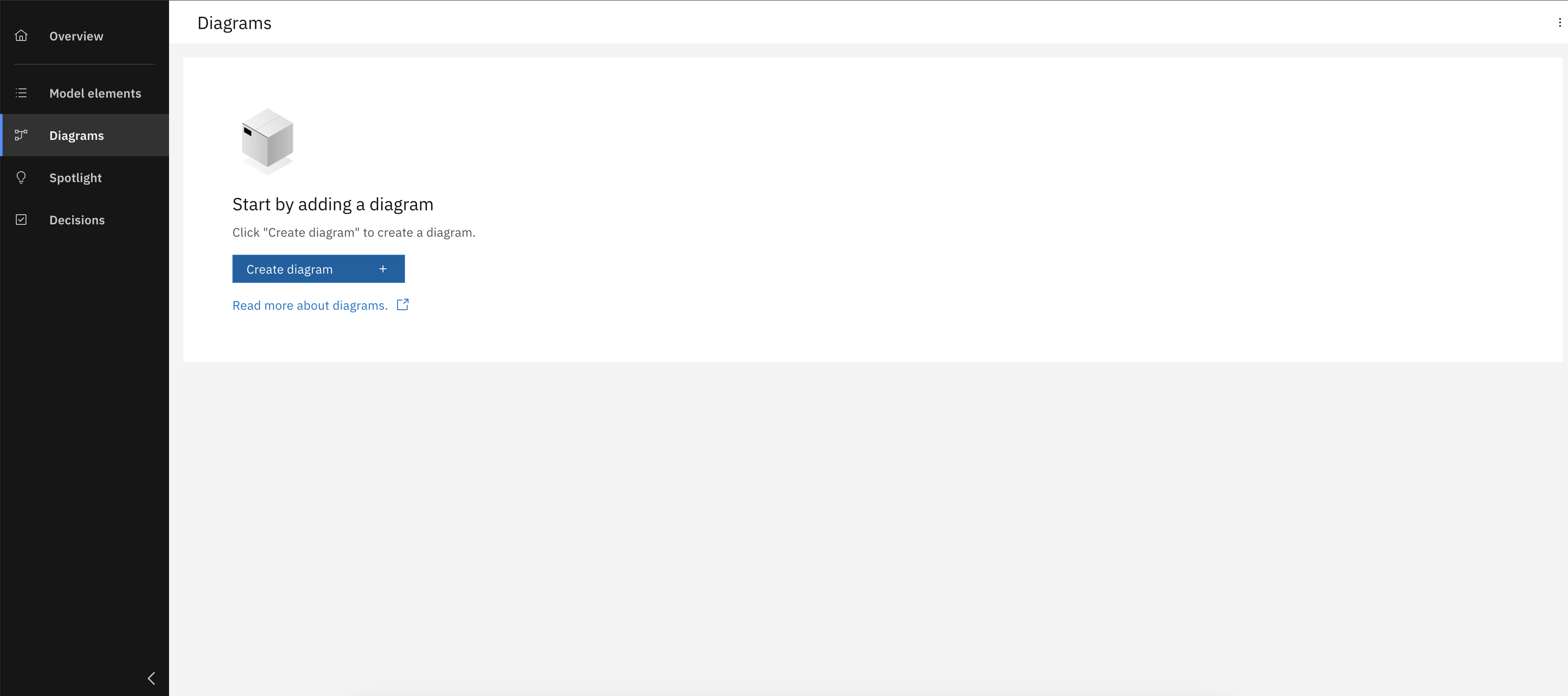
Create a new System Context diagram
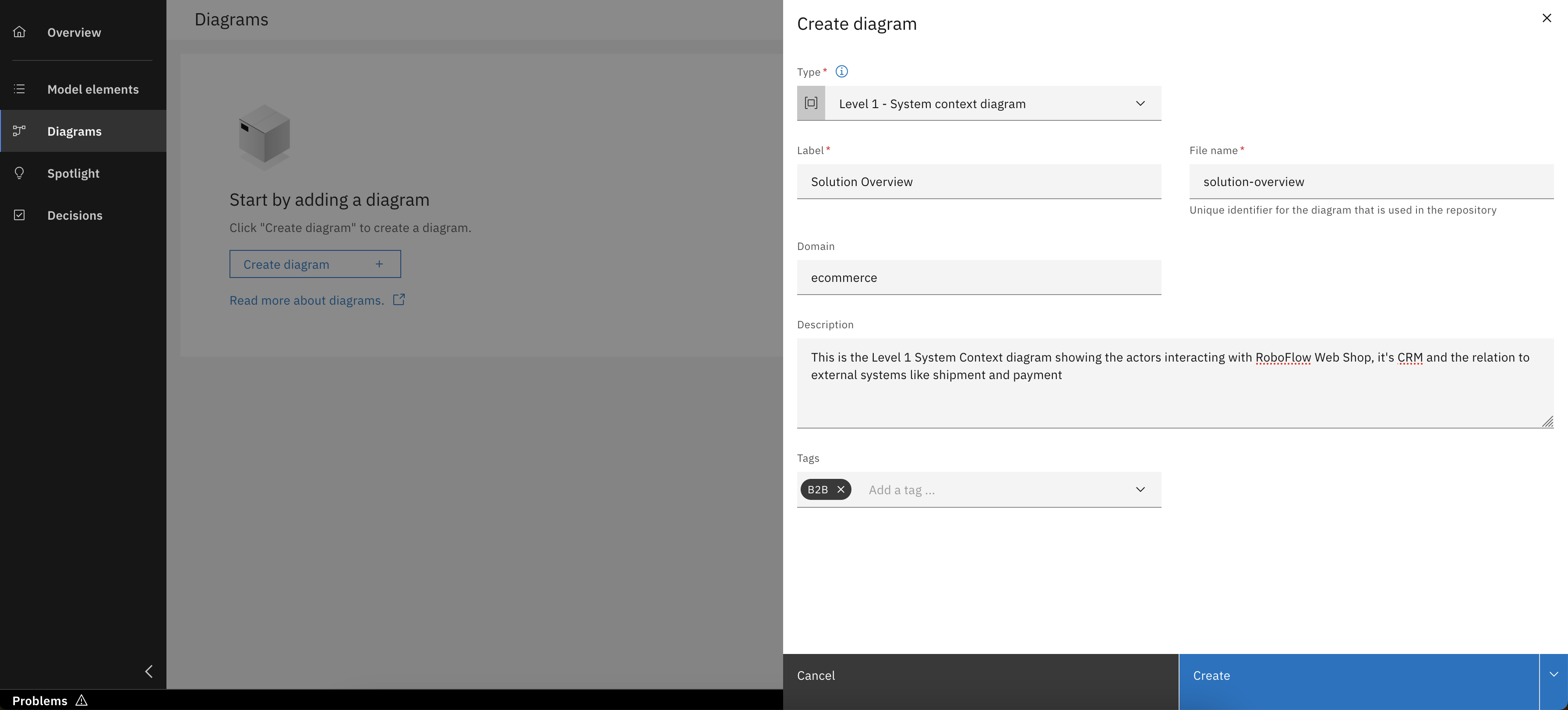
Enter diagram details and click "Create"
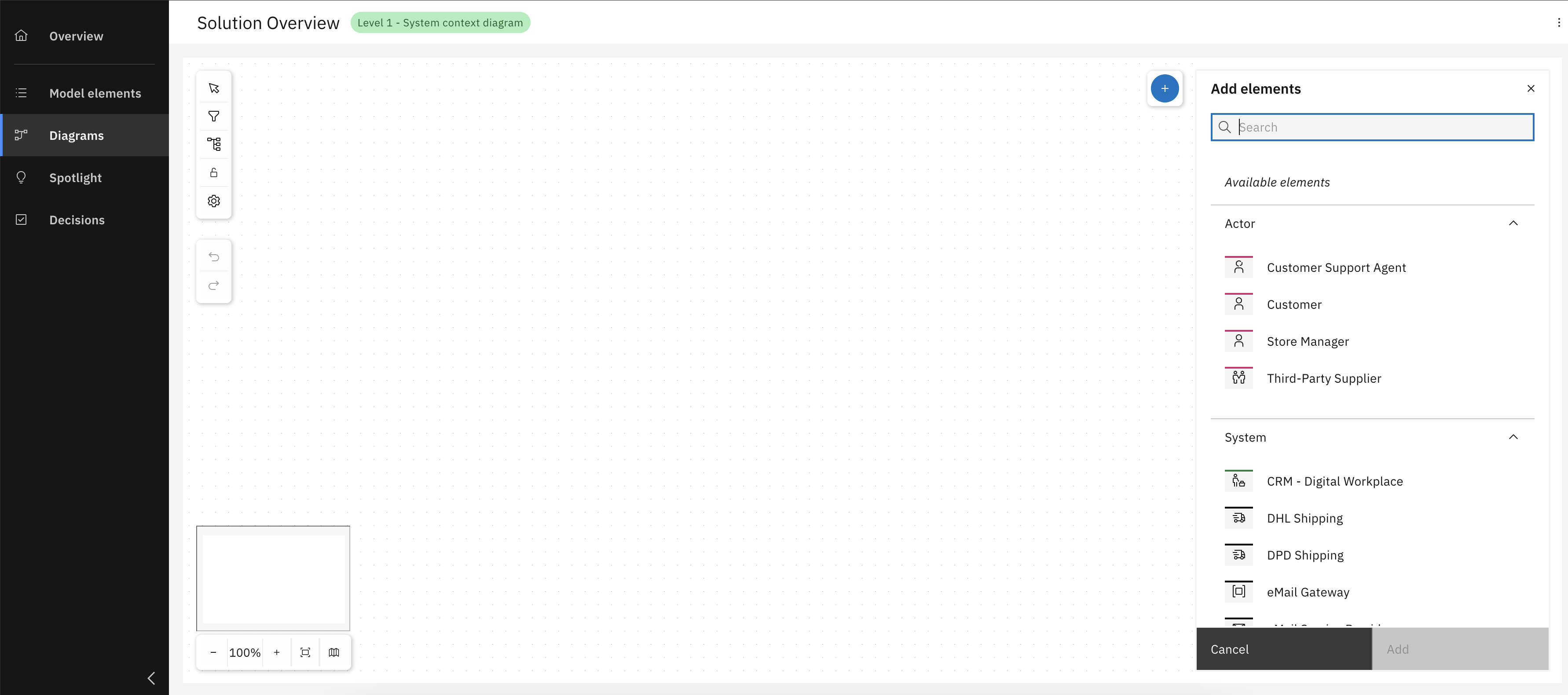
Open diagram and review available model elements, then add your model elements
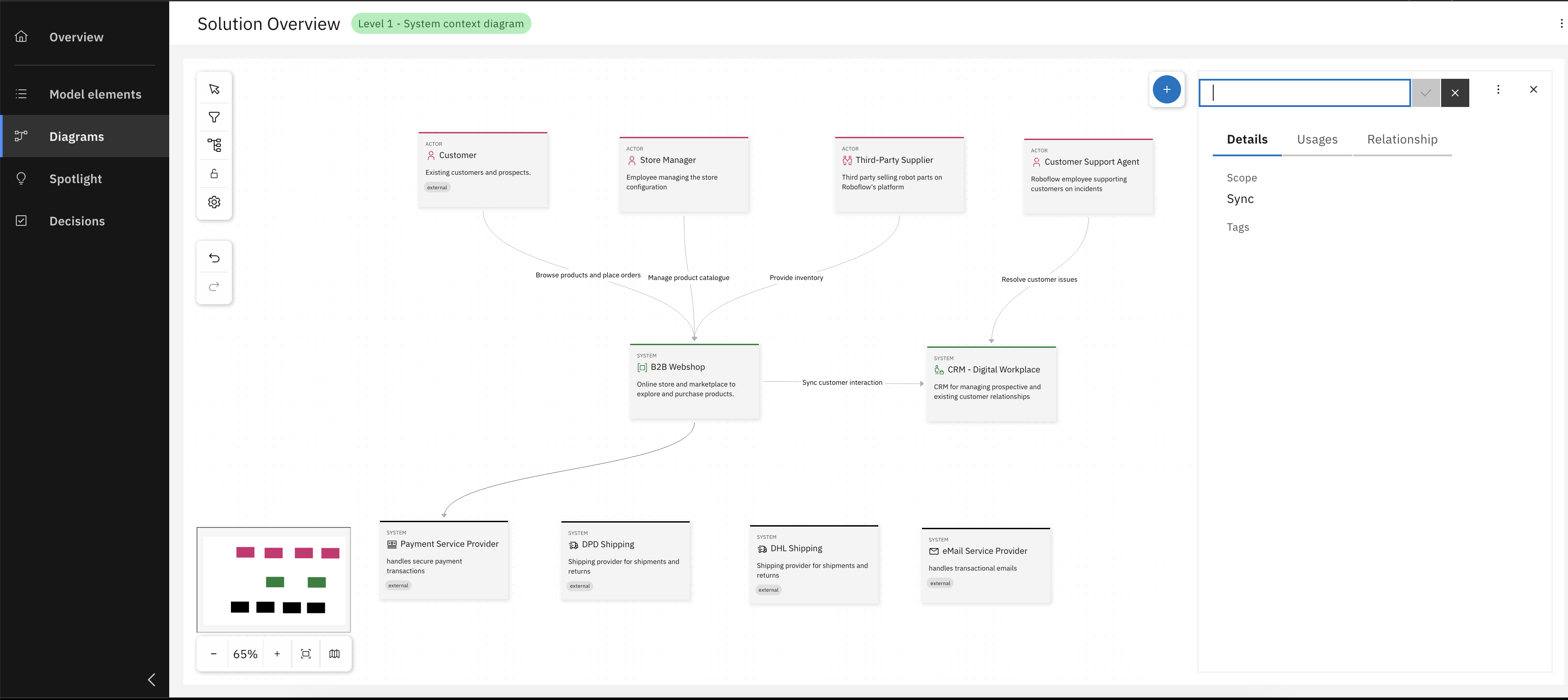
Add relationships between the elements
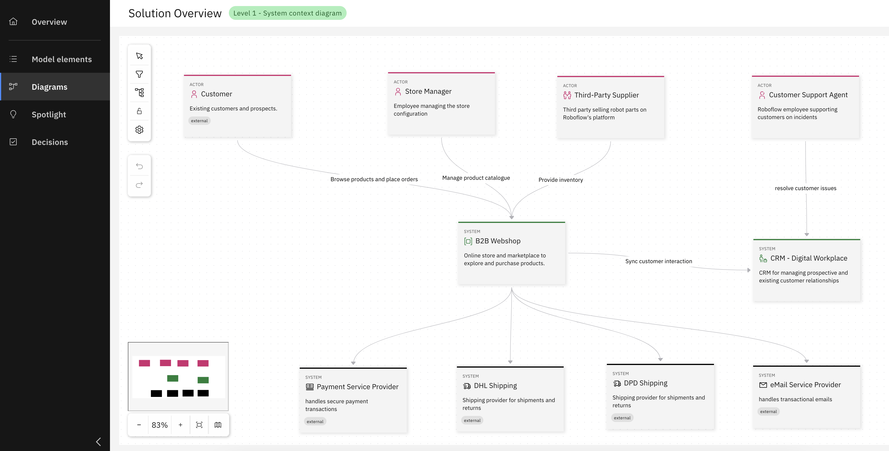
Congrats, you have successfully created your System Context diagram
Step 2: Create a Container Diagram
After creating the system context diagram, the next step is to develop a container diagram for the defined internal system. This involves detailing the internal architecture by identifying containers, their responsibilities, and how they interact. As before, the example continues with the RoboFlow scenario, but feel free to adapt the steps to your own context.
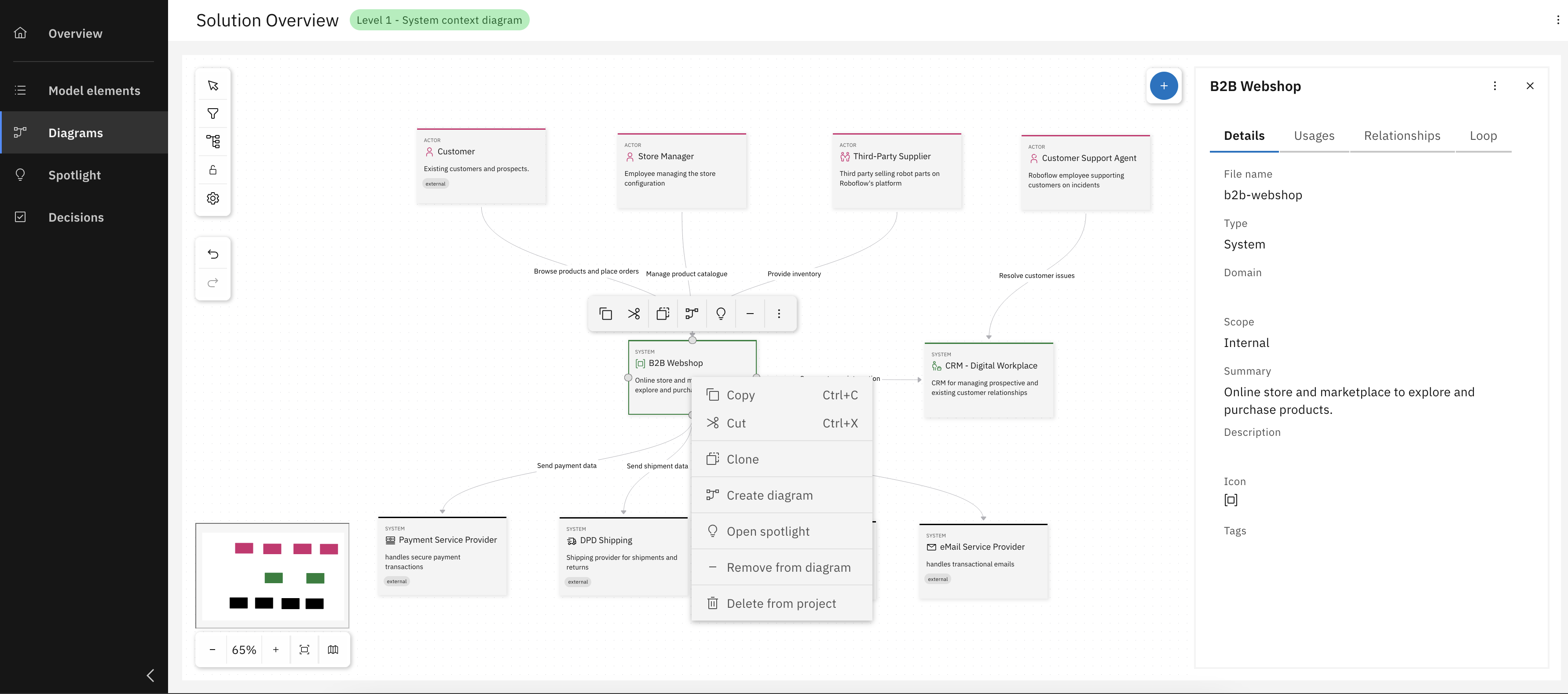
Right-click on B2B system box and click "Create diagram"
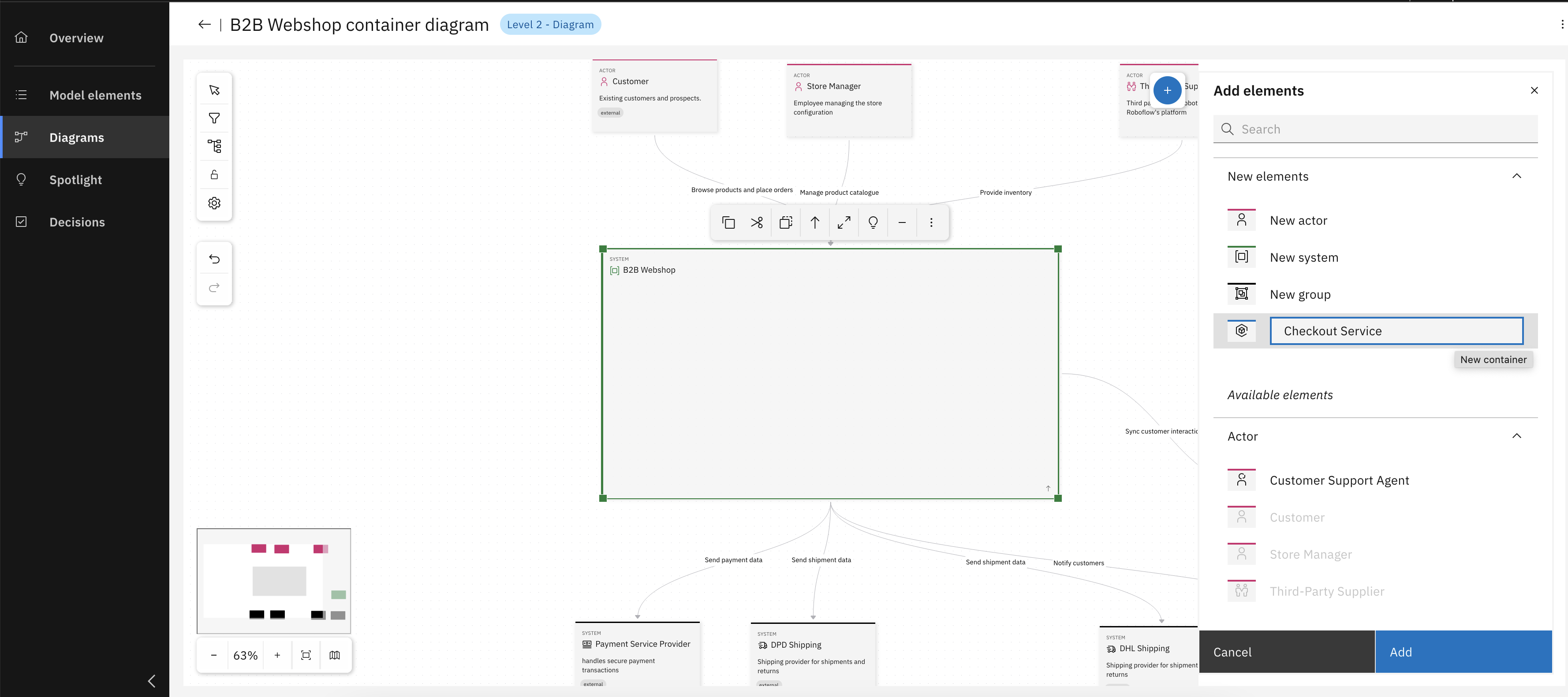
After Level 2 diagram creation, add necessary containers
Add more containers and establish relationships between them
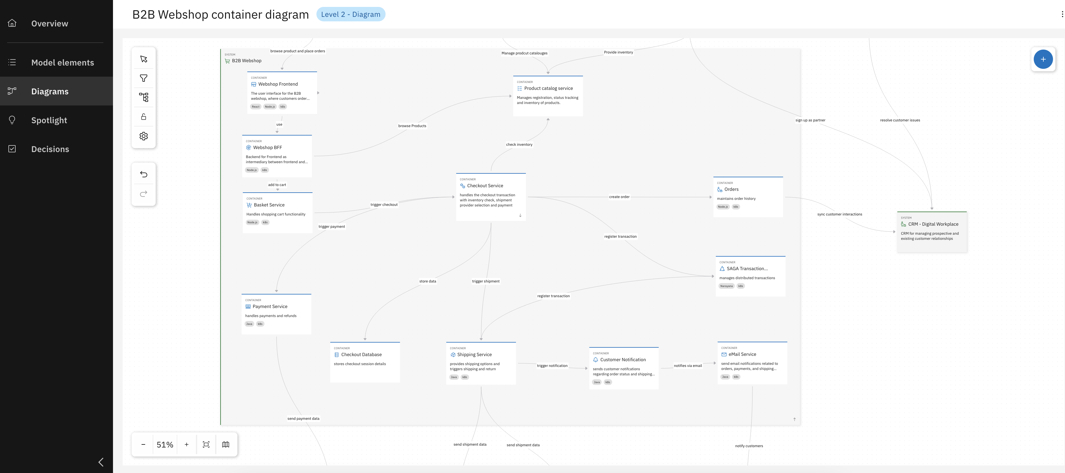
Congrats, you have successfully created your Container diagram for the B2B webshop
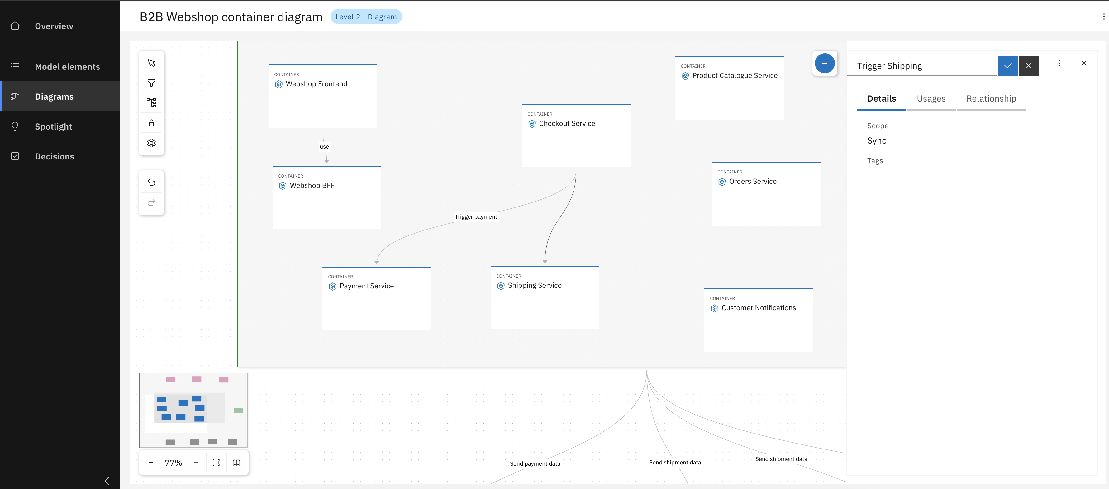
Step 3: Create a Component Diagram
Lastly a level 3 diagram - a component diagram - needs to be created based on a previously defined service container. This step involves zooming into a specific container to define its internal components and map out their relationships.
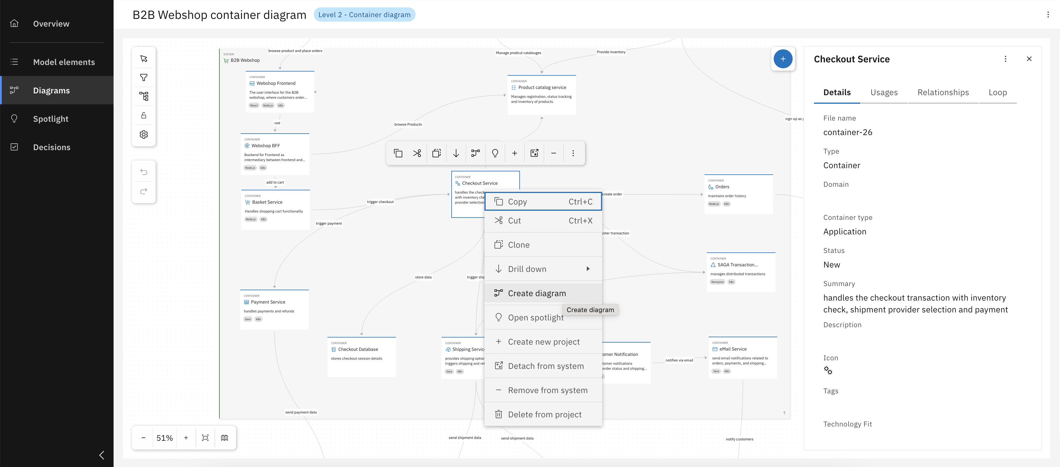
Right-click on Checkout Service box and click "Create diagram"
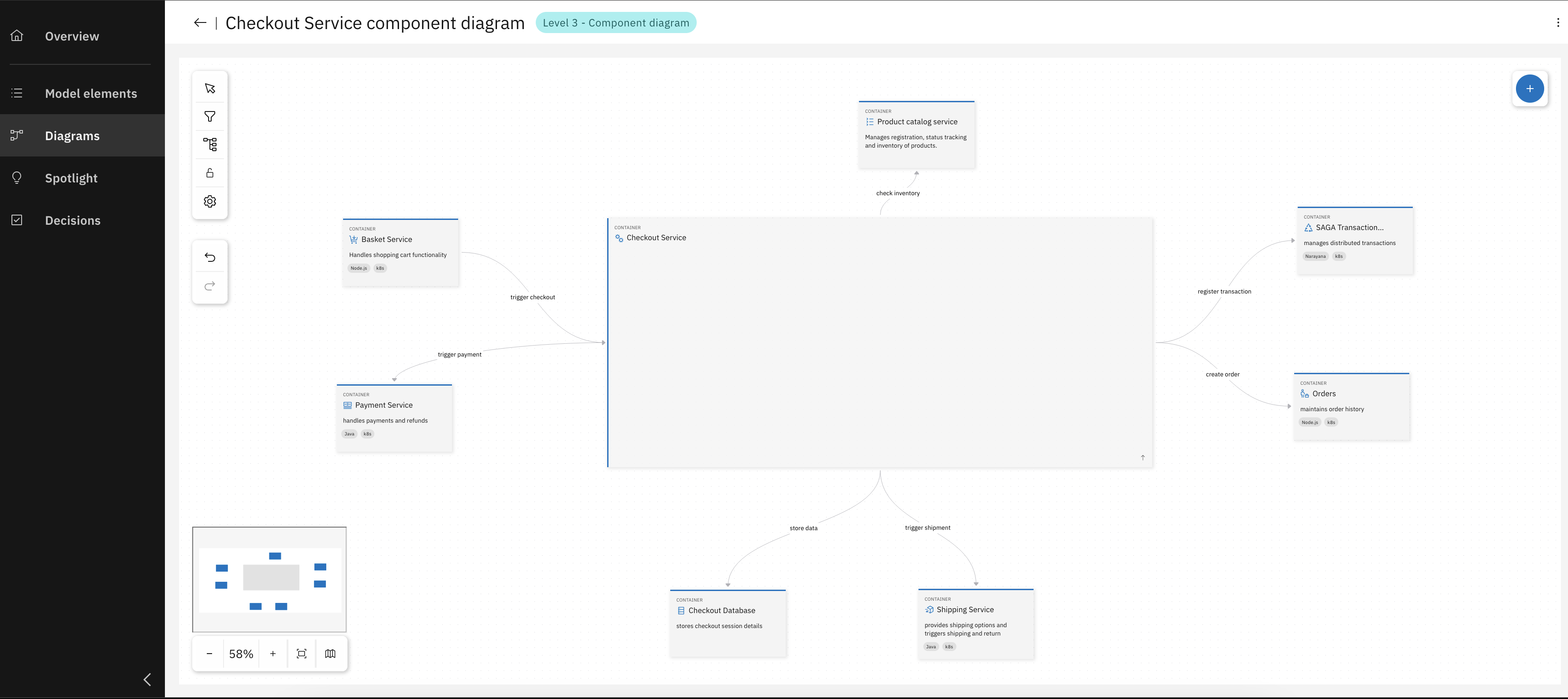
New level 3 diagram Created, with existing connections to other servcies
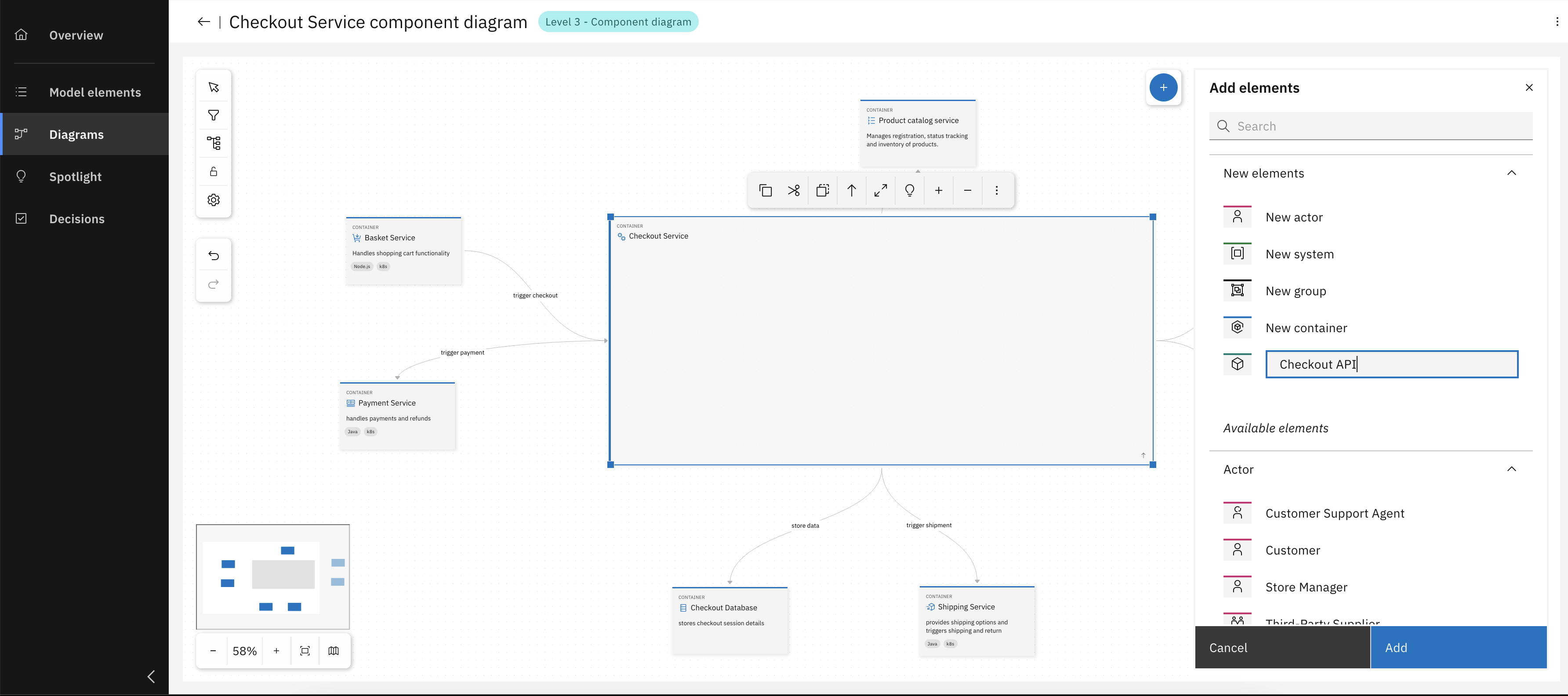
Add components with relevant details
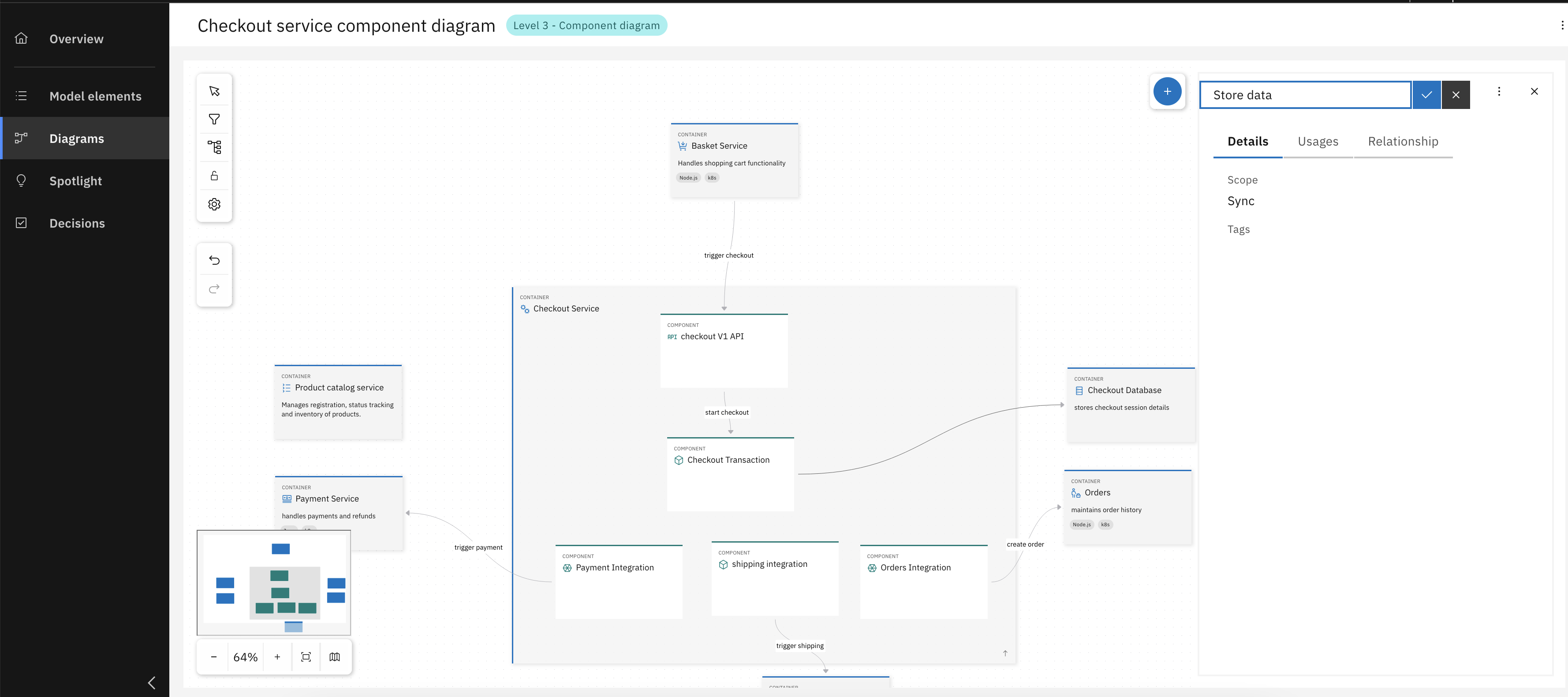
Model relationships between components
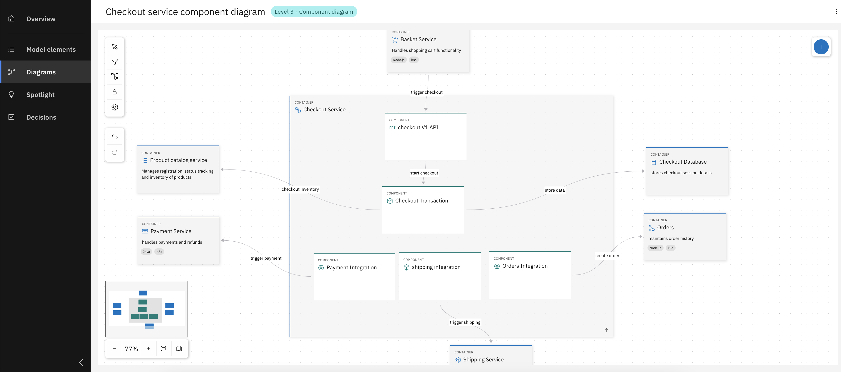
Congrats, you have successfully created your Component diagram for the Checkout Service.
Loop, Links and Relationships
Effective architecture is more than a list of components. It's a dynamic network of relationships between elements and the decisions that shape them. This section explores how the IBM DevOps Solution Workbench helps you define, visualize, and manage these critical connections. By creating these links, you can capture the bigger picture of how architecture evolves: from strategic choices to technical implementation, and ensure that nothing important gets lost between design and delivery. In this part of the unit, you will:
- Link architecture to implementation projects and decisions (Loop) to provide traceability from high-level intent to concrete work items.
- Attach external references (Links) to enrich your model with any relevant resources your team needs.
- Analyze connections with Usages and Relationships views to identify dependencies and potential impact of changes.
Exercise - Loop and Relationships
- Estimated time: 10 Minutes
- Exercise goal: You're able to use Loops, Links and Relationships.
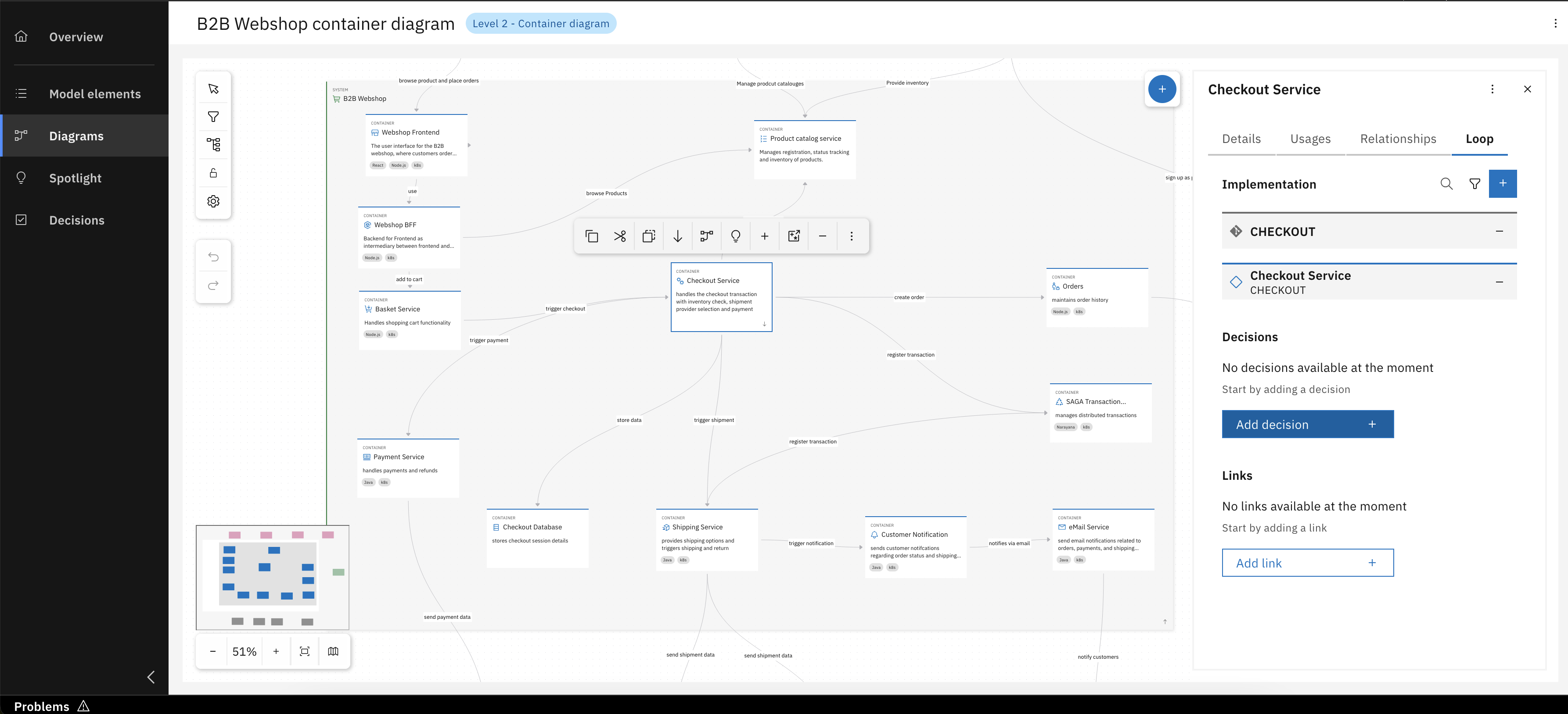
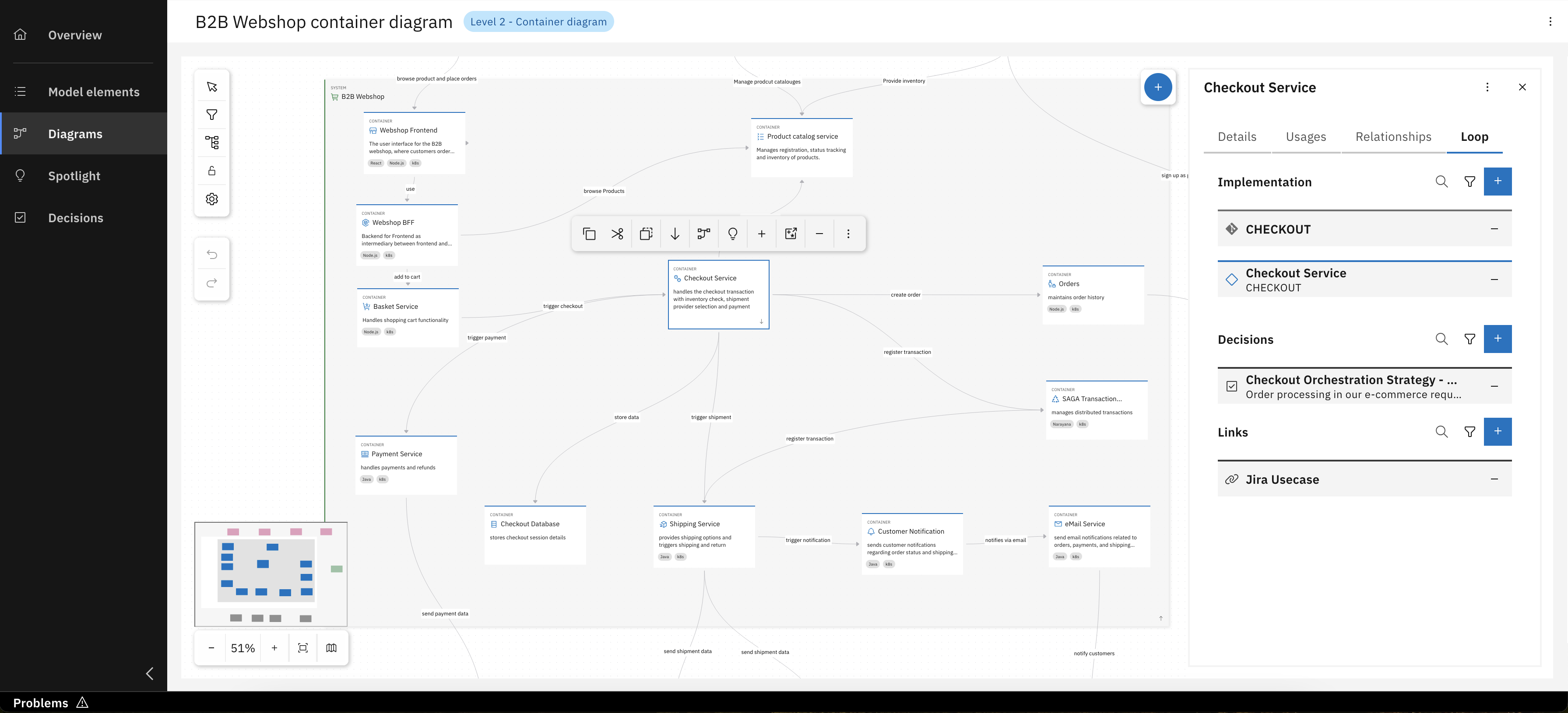
Step 1: Loop and Links
Let's now focus on the Loop tab for our Checkout Service, first we add a link to it's implementation project.
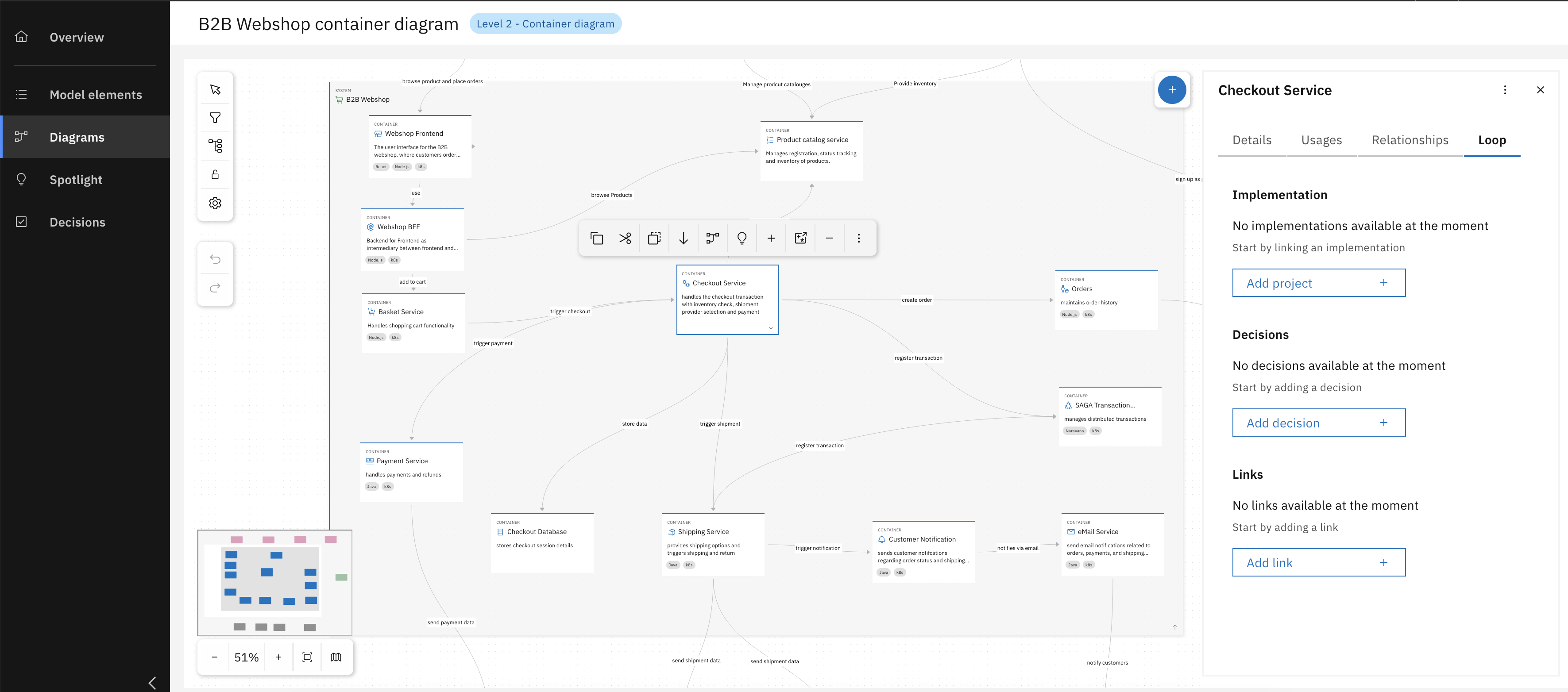
Navigate to Loop tab inside the Checkout Service
Click "Add project"
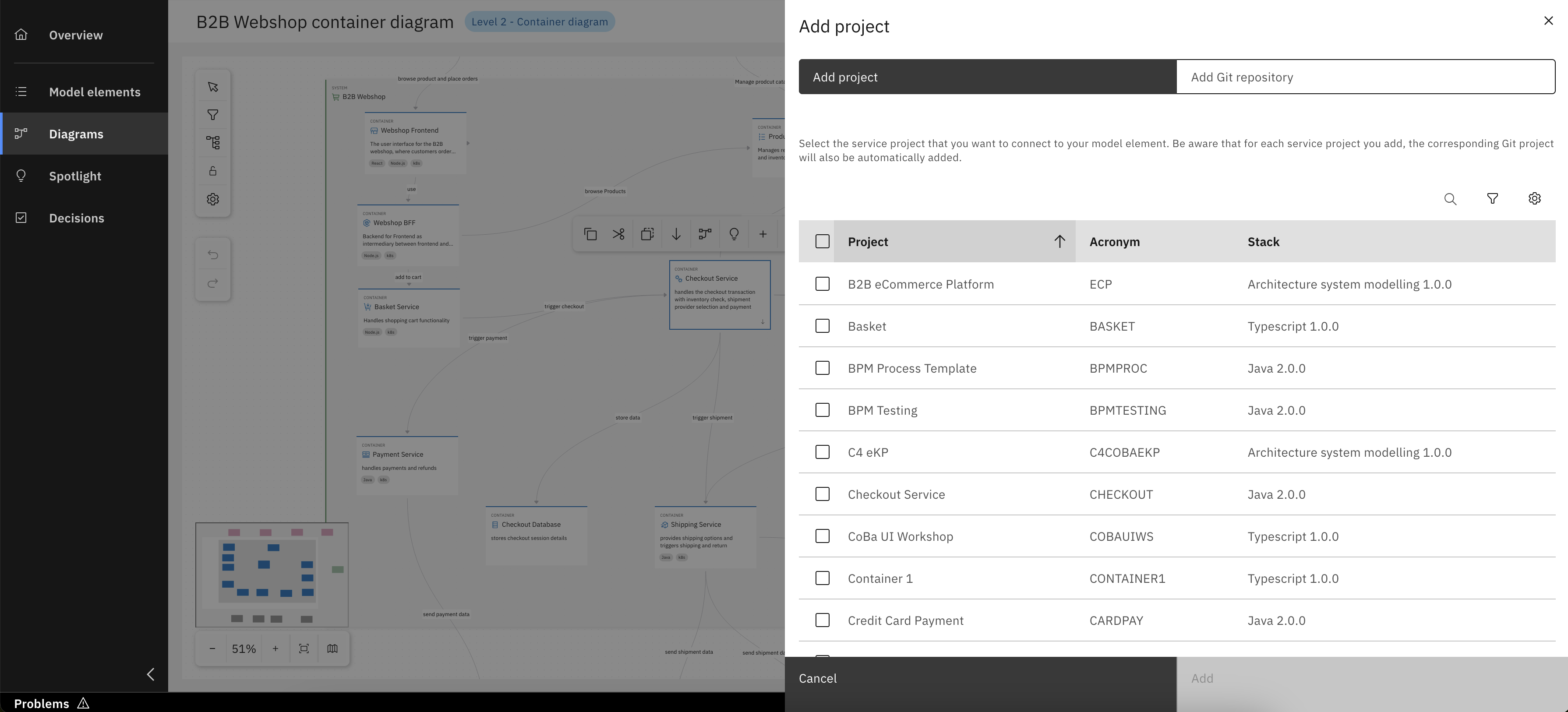
Either select Workbench project
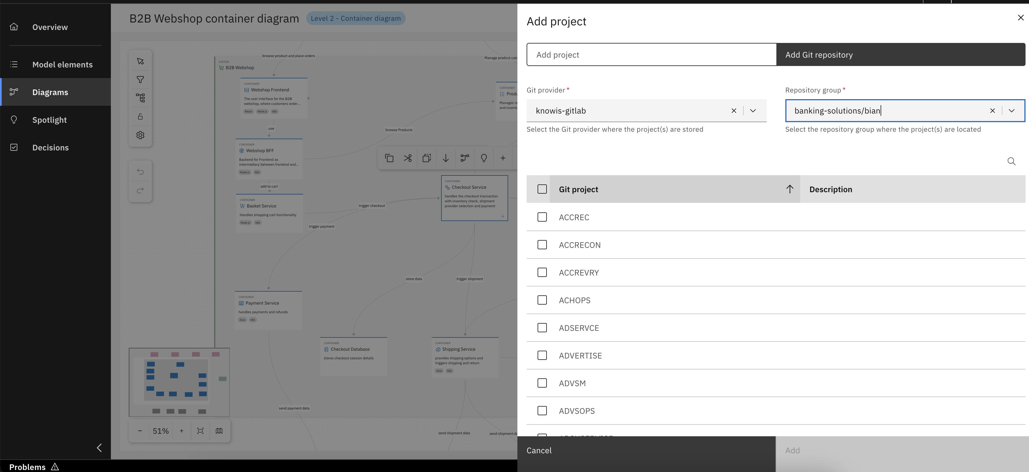
Or a project from configured Git
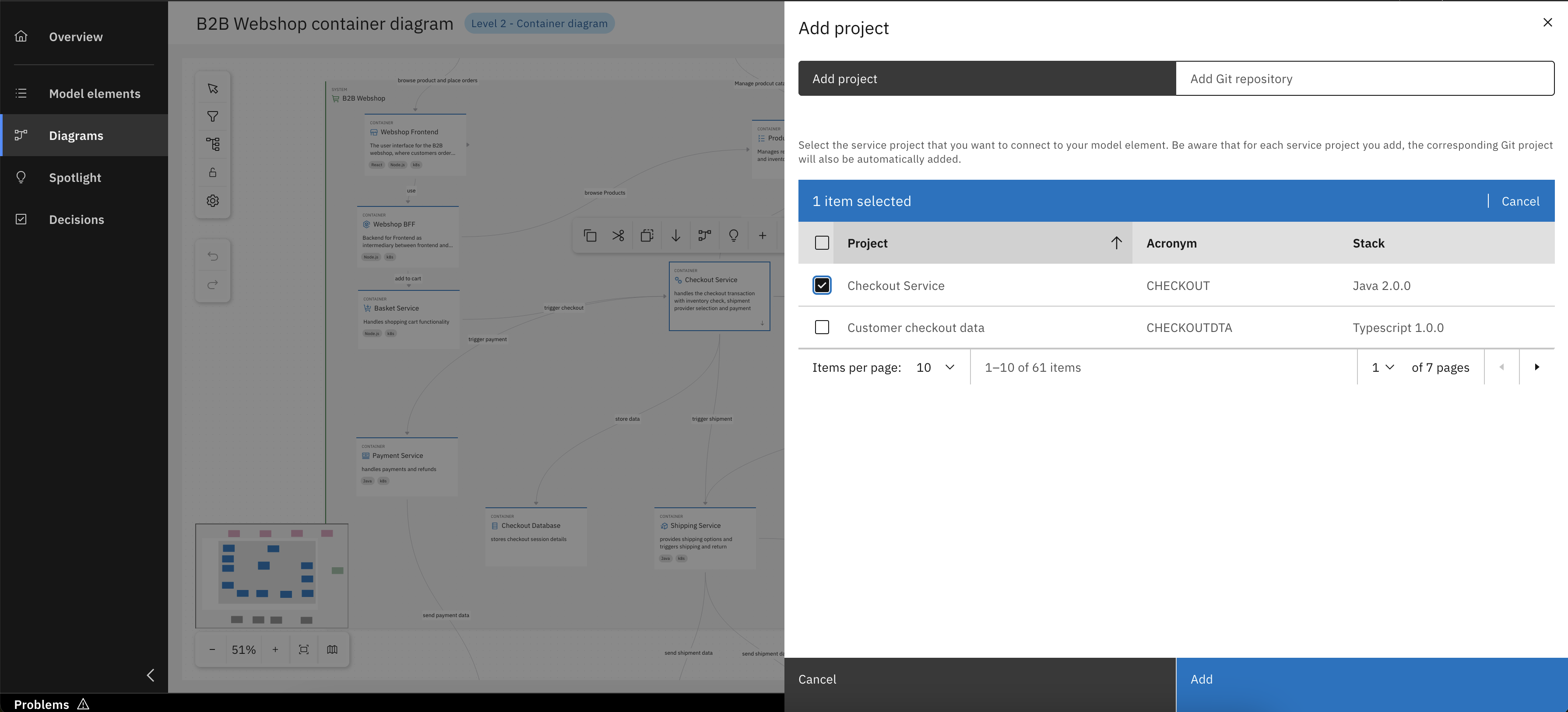
In our case select the Checkout Service and click "Add"
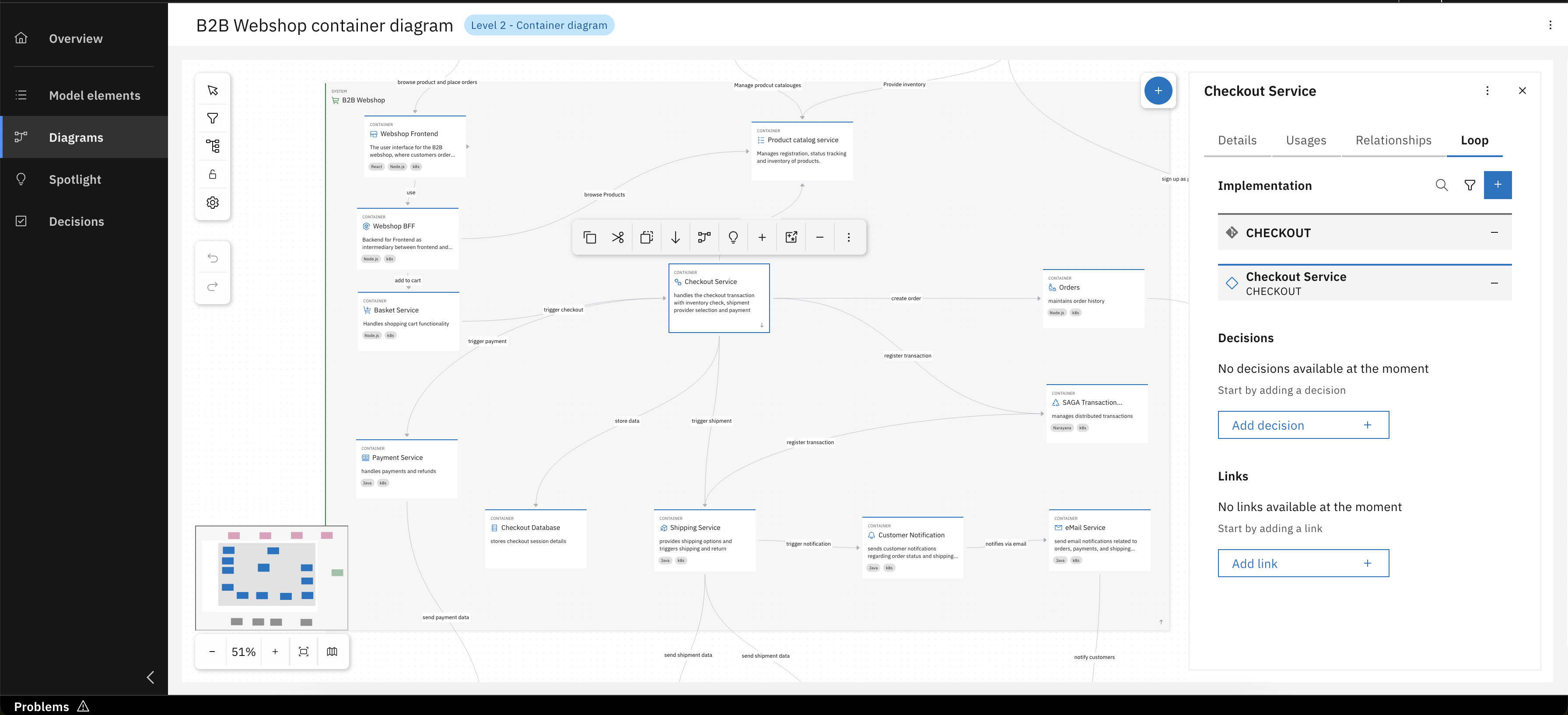
Congrats, you have successfully linked Checkout Service implementation project
You can also create a new Workbench project directly from a container's context menu.
From the Loop tab for your Checkout Service, you can manage its associated Architecture Decisions. This means you can link to existing decisions that are relevant, ensuring its design is always connected to the documented rationale and guiding principles.
Click "Add decision"
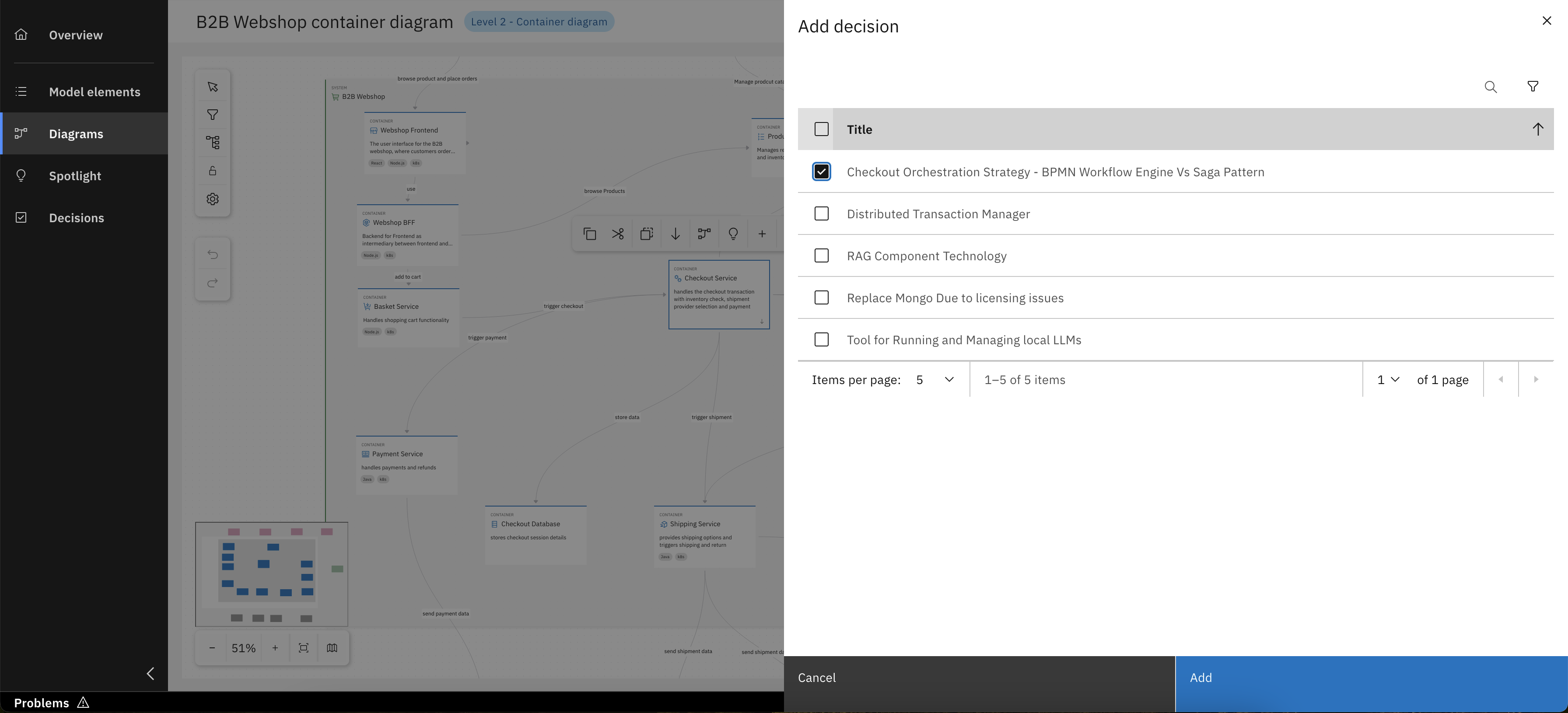
Select one or more Architecture Decision(s)
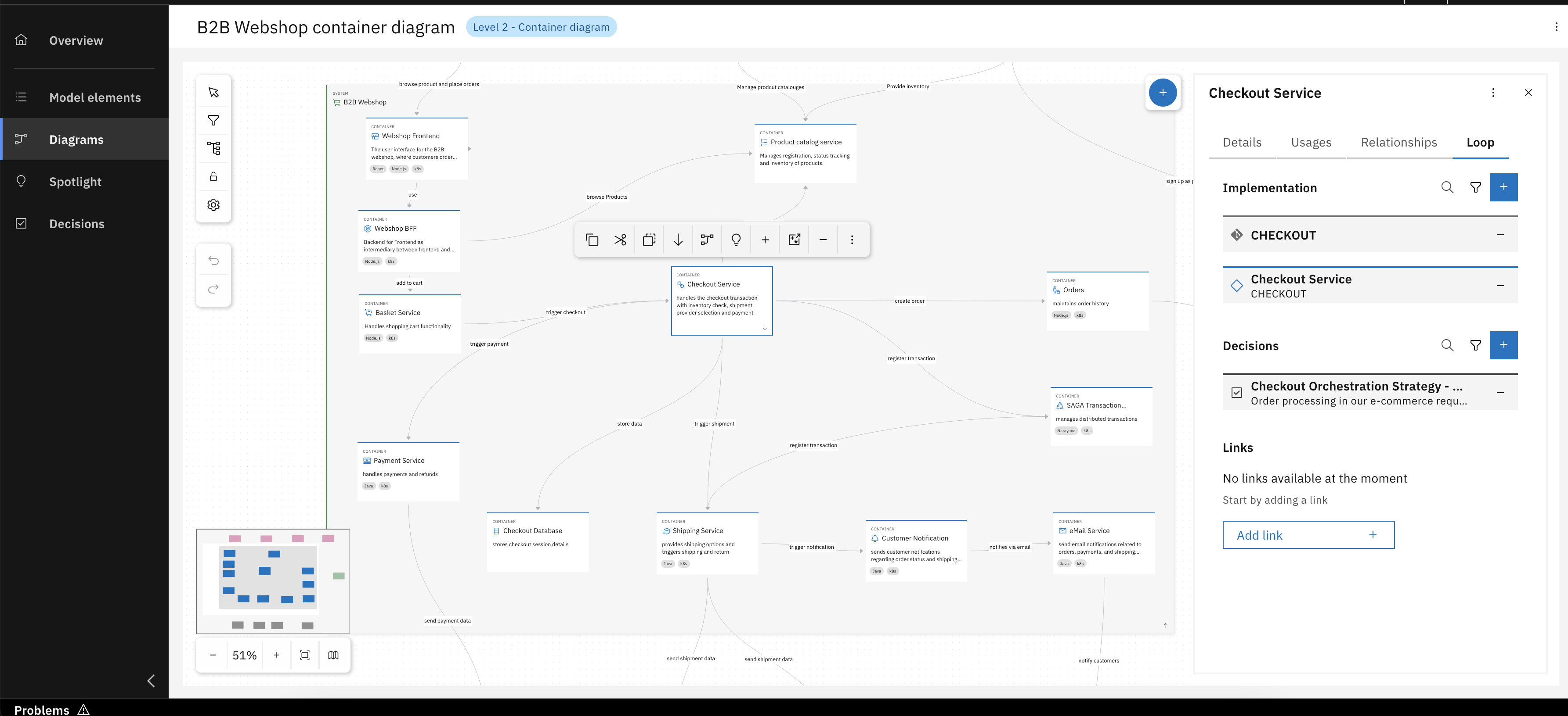
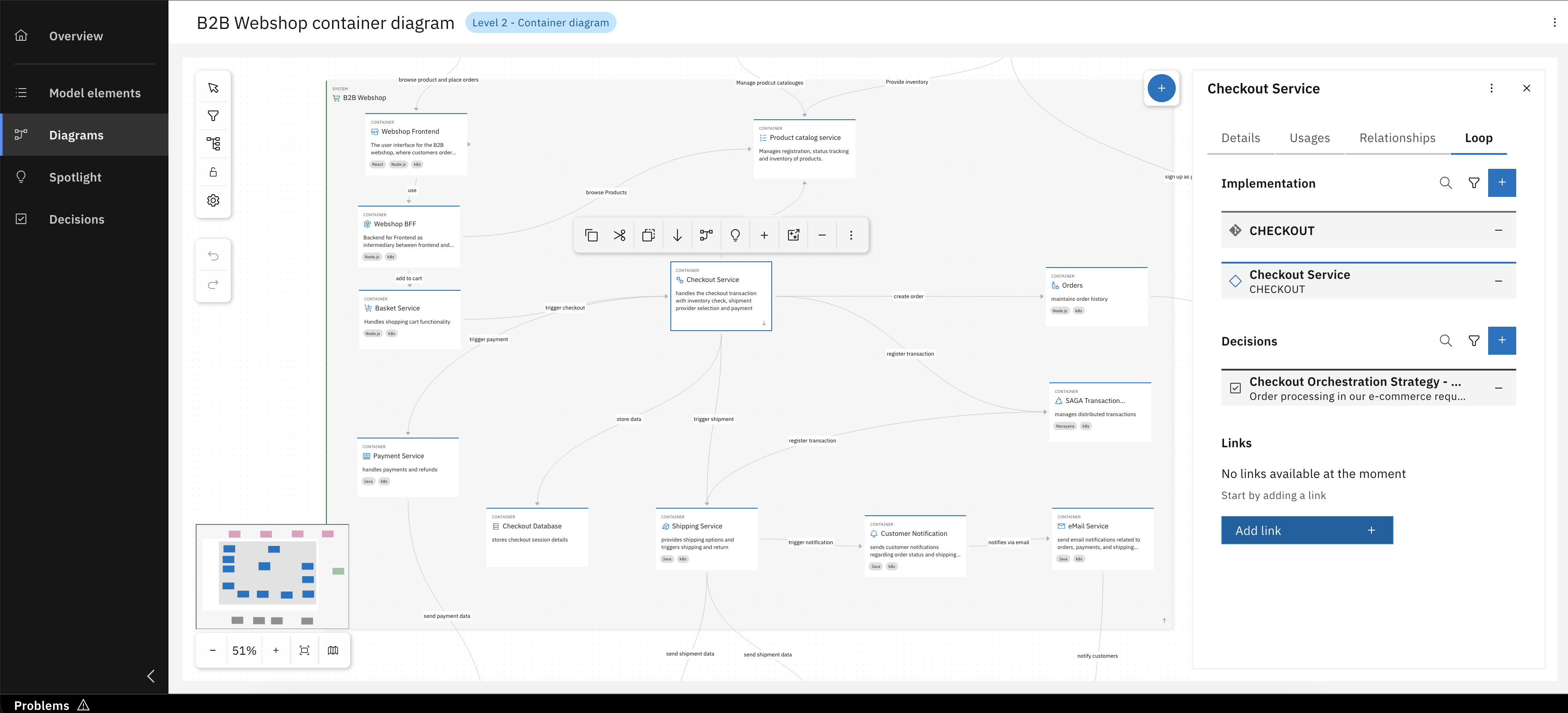
Congrats, you have successfully linked Architecture Decisions
Last but not least, you can also manage associated links inside of the Loop tab. This means you can link to external links that are relevant, adding more documentation, context and information.
Click "Add Link"
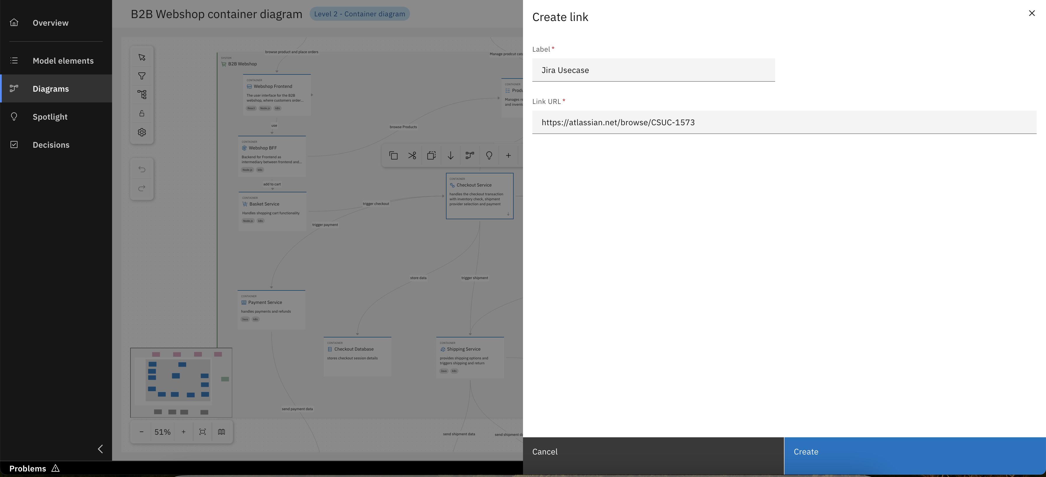
Add relevent details and click "Create"
Congrats, you have successfully added external links
For detailed instructions on the comprehensive process of creating new architecture decisions, please refer to Unit 4.
Step 2: Usages and Relationships
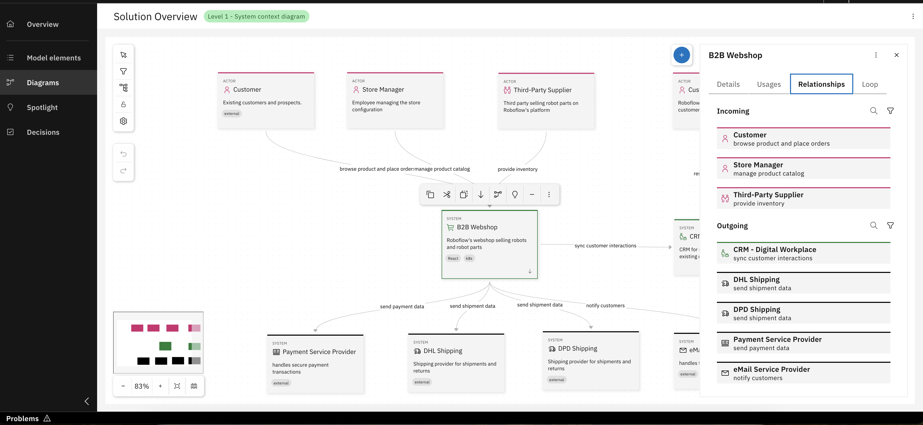
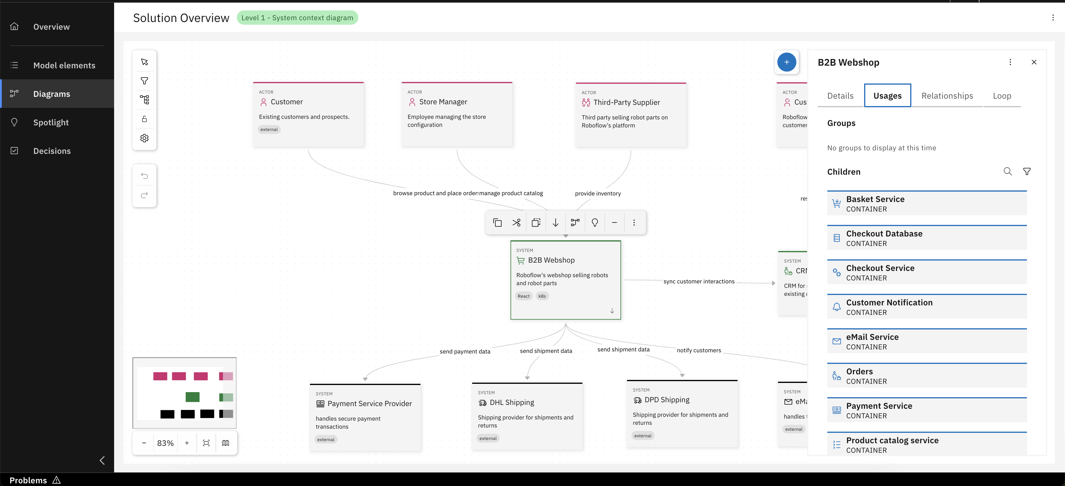
Understanding how a model element is connected within the architecture is essential. The Usages and Relationships tabs provide insight into these connections:
- Usages: Displays where the selected model element is already in use. This includes diagrams where the element has been added, as well as its inclusion in higher-level elements, such as systems (for containers) or containers (for components). It helps you track how and where an element is being reused.
- Relationships: Lists all model elements that are used as “source” and “target” of the selected model element. These relationships represent interactions with other elements in the project and are visualized in diagrams as arrows between element cards. Clicking on an entry in this tab highlights the corresponding element in the diagram canvas.
What's next?
In the upcoming unit, you will explore all around creating and customizing Architetcure Decisions in the IBM DevOps Solution Workbench in greater detail. You can also explore existing applications and modeling examples here.