Unit 2: Working with Model Elements and Diagramming
In this unit you will learn to work with model elements and create your first diagrams. We use the C4 framework to keep the architectural design process deliberately lightweight, encouraging creativity and collaboration. By keeping things simple and focused, IBM DevOps Solution Workbench helps teams work together to explore and refine ideas, ultimately arriving at the best possible solution.
Outline
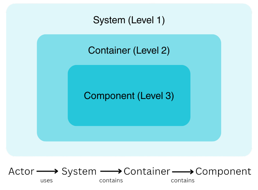
Model elements represent parts of a software architecture and the relationships between them. Following the C4 methodology, these elements are categorized into actors, systems, containers, and components. Additionally, elements can be visually grouped using a group. Below is an overview of the different model elements:
| Model Element | Level | Description |
|---|---|---|
| Actor | 1 | Human or role that interacts with the system |
| System | 1 | Software system under consideration or external |
| Container | 2 | Deployable application/service/data store |
| Component | 3 | Logical grouping of related functionality |
| Group | All | Visual layout / grouping aid |
Visually, the structure can be represented like this:
For more in-depth information about model elements and their relationships in C4 models, you can check out our Product Documentation. There, you will also find other profiles that are available in IBM DevOps Solution Workbench.
Prerequisites
- Have a system architecture design project ready in place.
Exercise
- Estimated time: 15-20 Minutes
- Exercise goal: You will be able to create model elements and work with diagrams after completing this unit.
Overview
In this exercise, we will use a scenario to guide us through the process of designing a system architecture. The scenario is based on the existing reference application, RoboFlow. Our goal is to create model elements relevant for the B2B webshop of the RoboFlow company, which aims to sell robots and parts online. Next, we will create an example Level 1 diagram, utilize the drill-down functionality, and develop a Level 2 diagram. Finally, we will demonstrate how to generate a service project directly from a diagram model element.
Starting from scratch as for our RoboFlow example, shows how the Workbench supports your workflow with top-down refinement, a key pattern for greenfield scenarios.
Step 1: Create model elements
For this exercise we need actors, the internal system itself and elements that the system interacts with. You also need to create Containers, such as the Frontend or a Shipping Service of your system. You can get inspiration from the RoboFlow app or refer to the last slide for guidance.
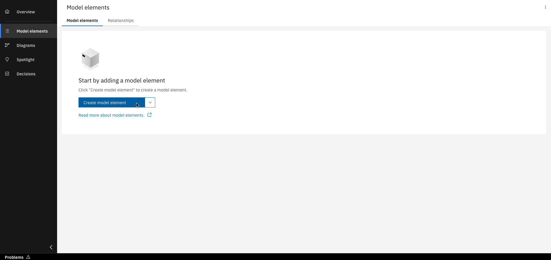
Click on "Create model element"
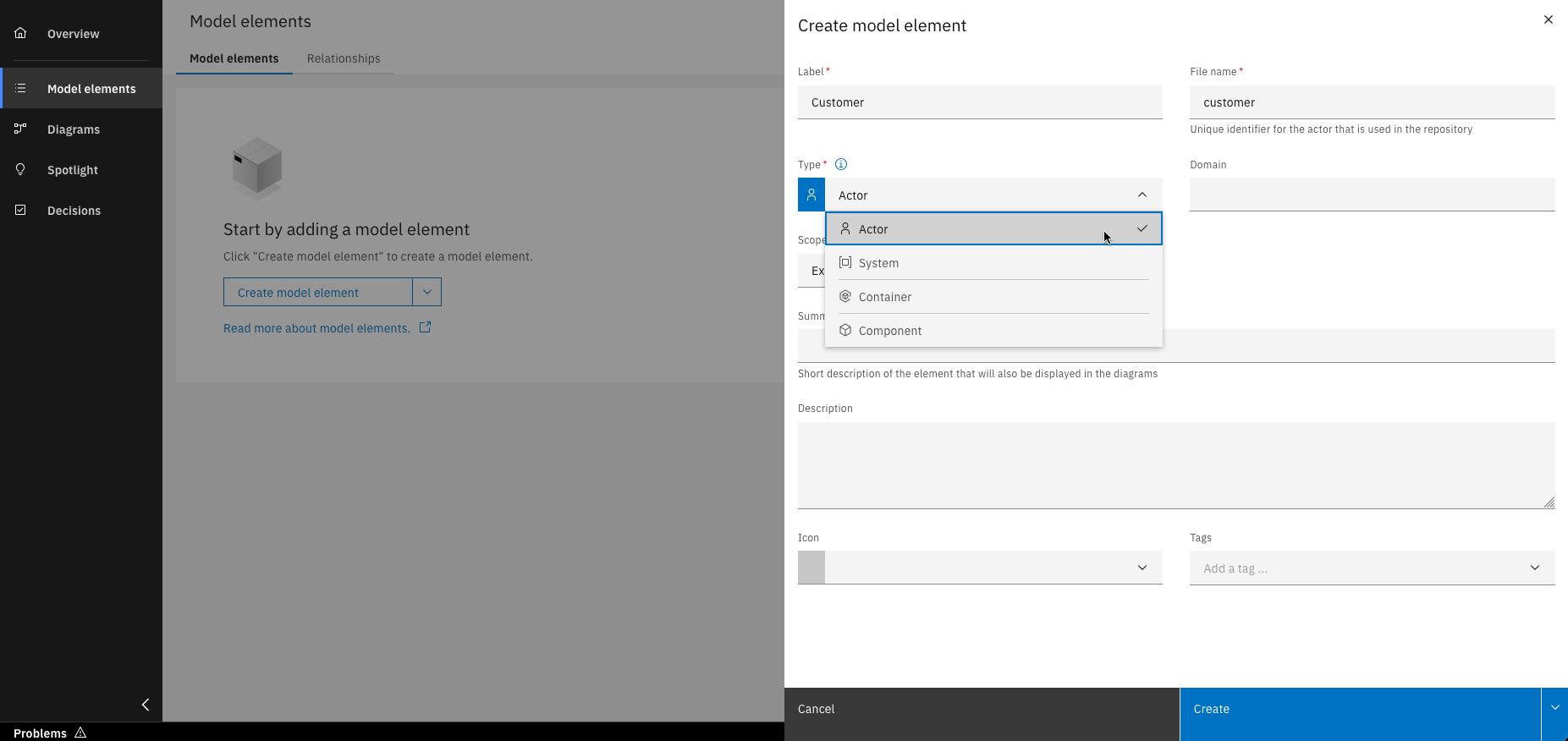
Use the "Type" dropdown menu to select the desired model element type

Fill in all required details and click "Create"
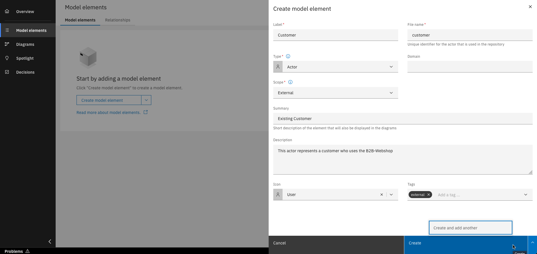
Alternatively, click "Create and add another" to keep the creation window open
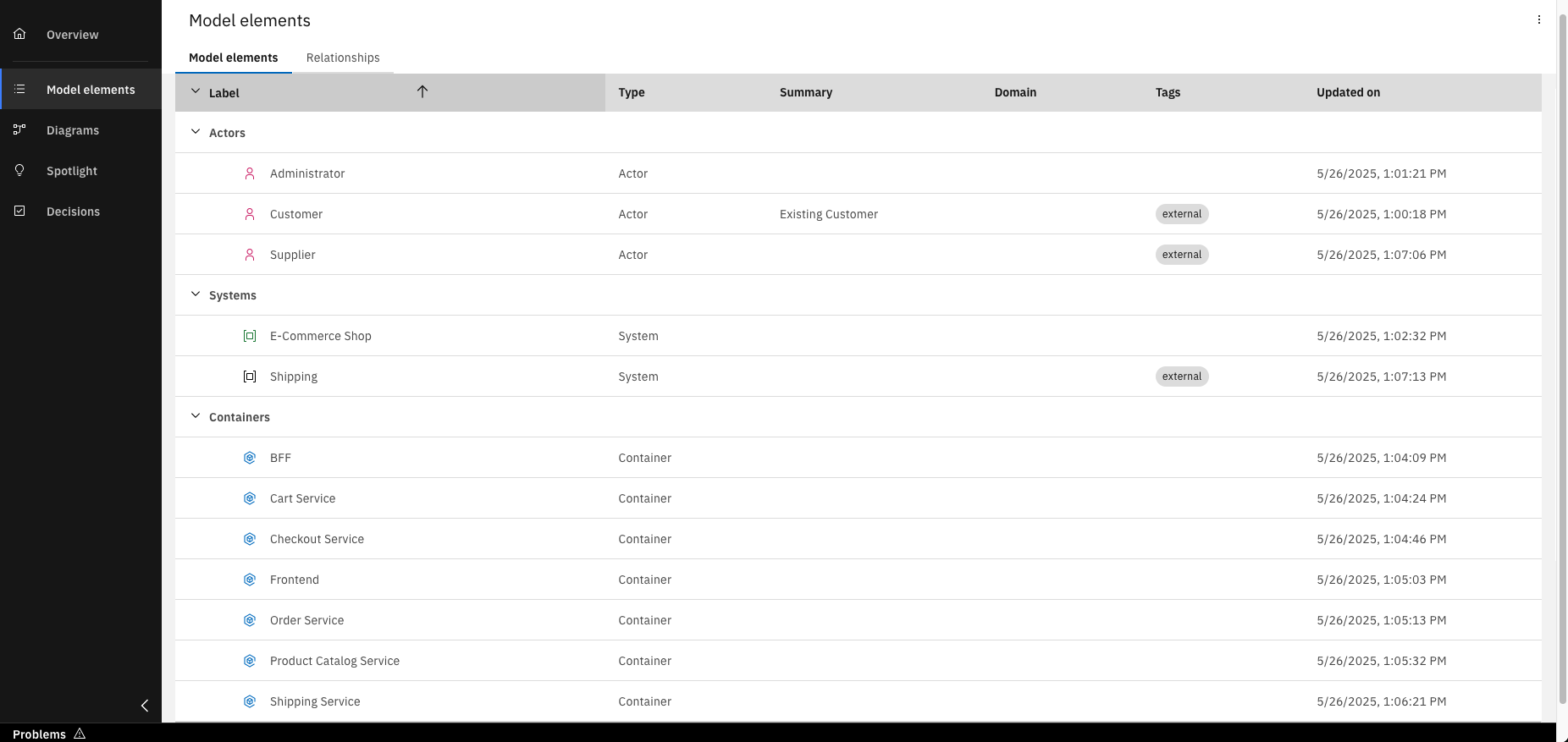
After creating the necessary model elements, an overview of all entries is displayed
You can also create model elements directly on the diagram canvas. Try it out in the next steps.
Step 2: Create a level 1 diagram
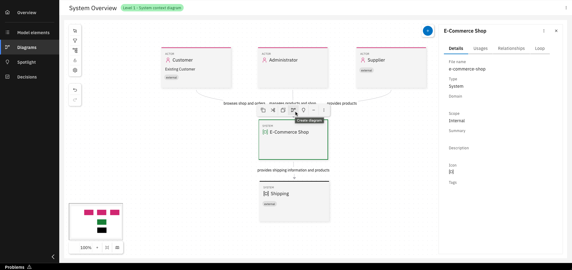
As we have all our needed model elements now, we want to create our Level 1 diagram, the model for the system context. This diagram allows us to see the big picture, how the system interacts with people and other systems.
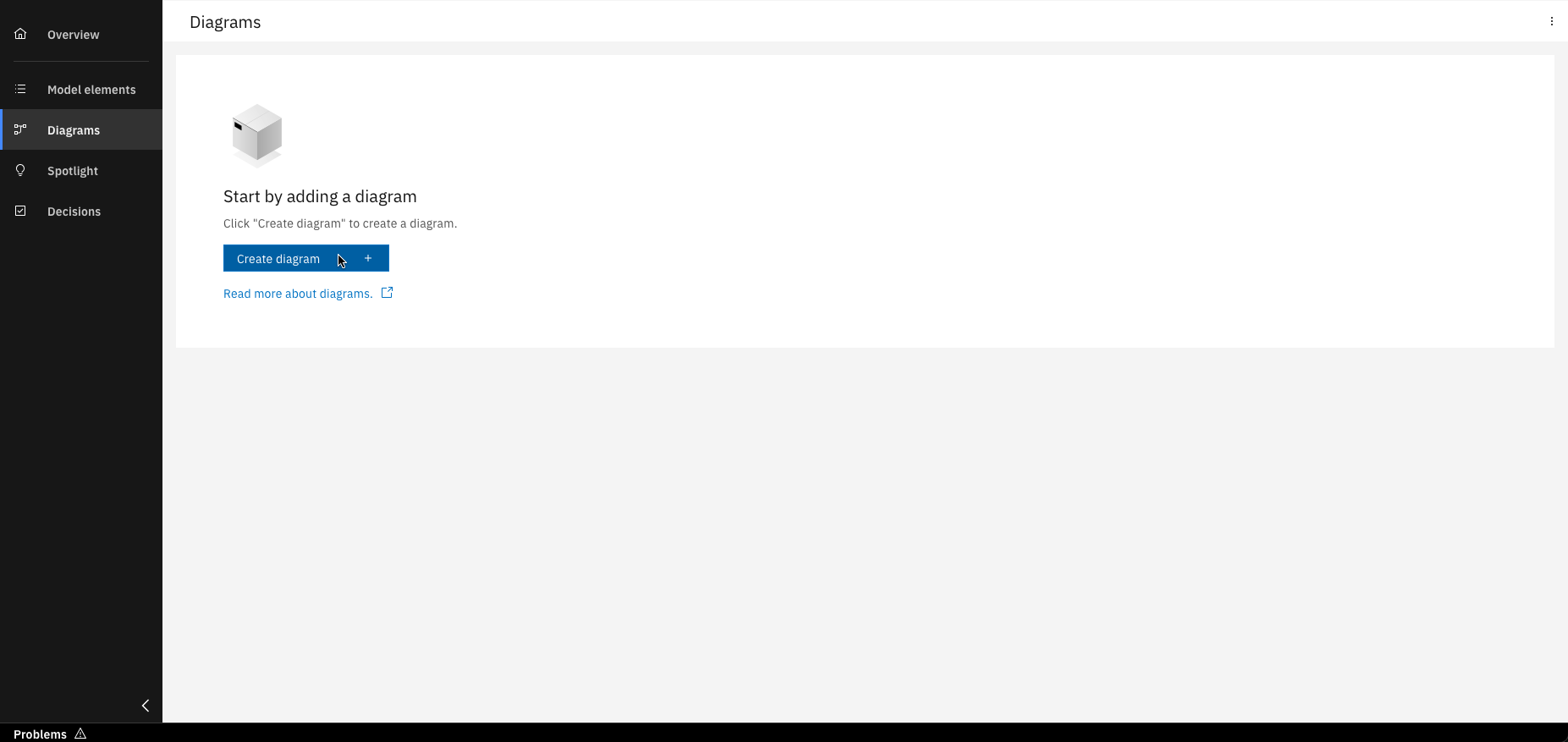
Click on "Create diagram"
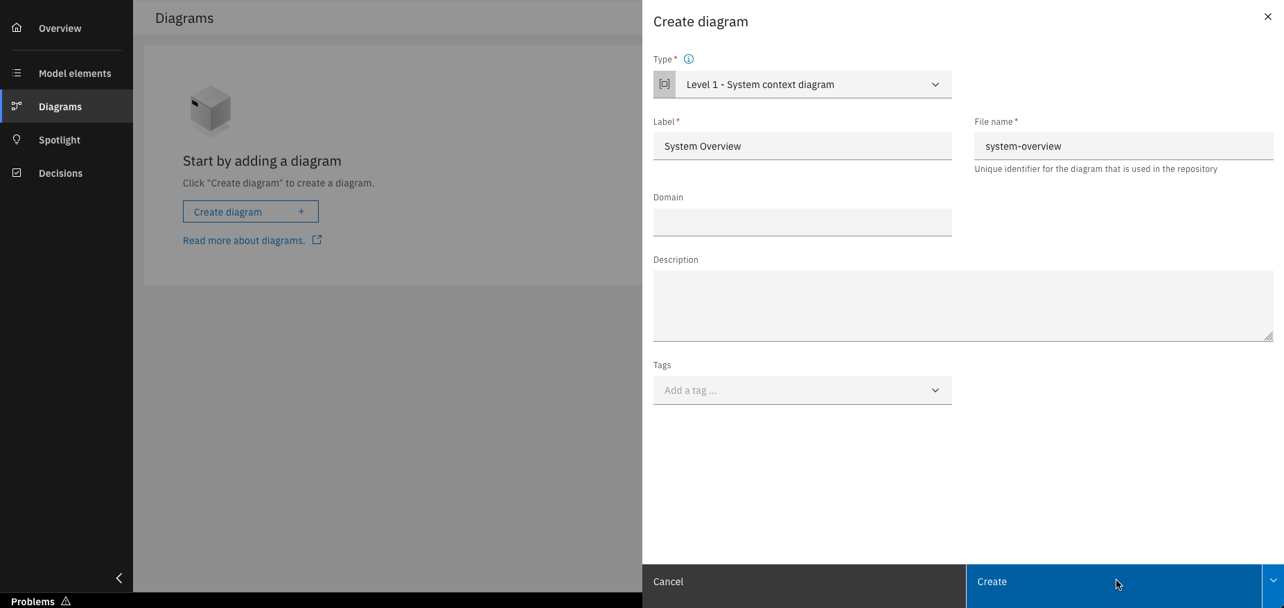
Fill in all required details and click "Create"
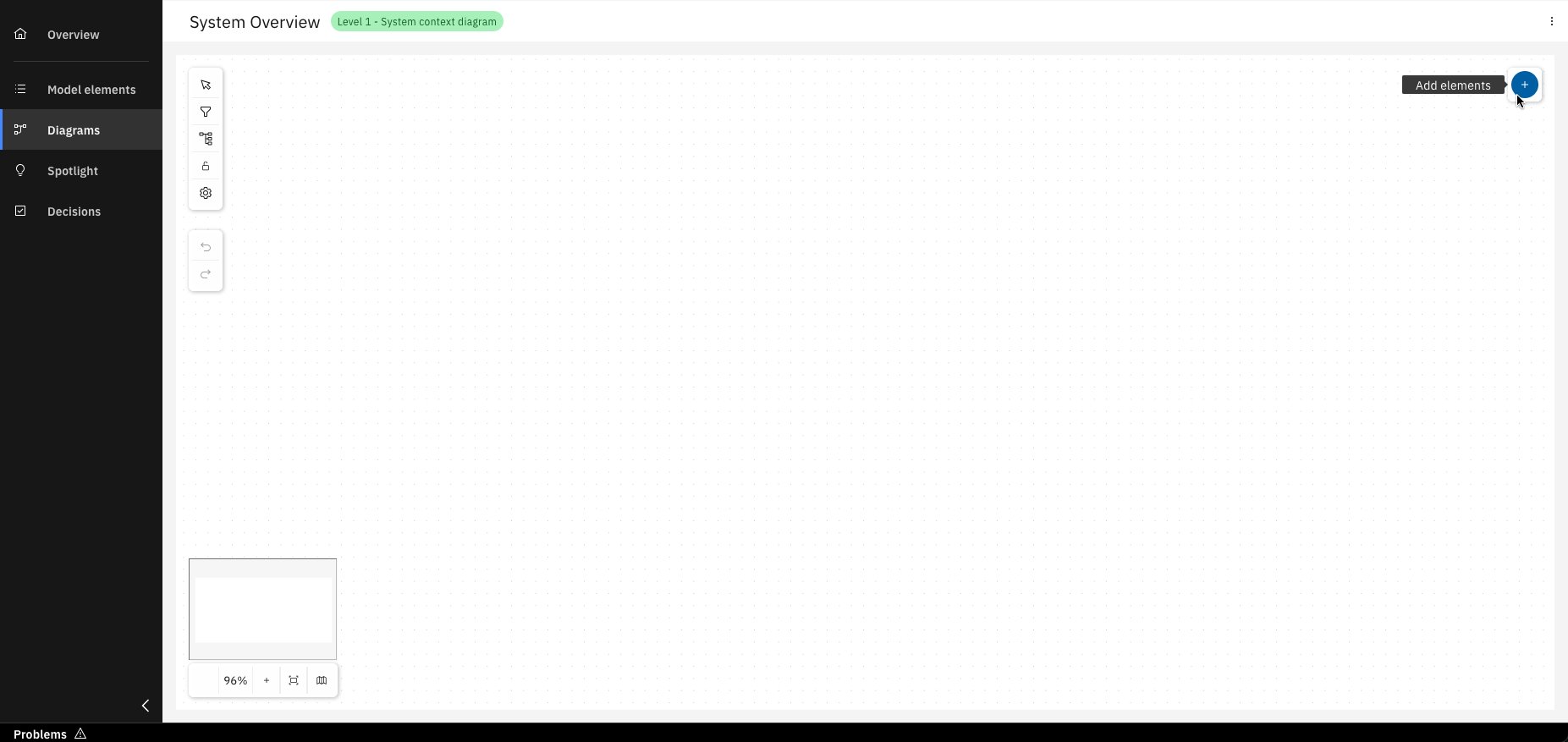
Click on "Add elements"
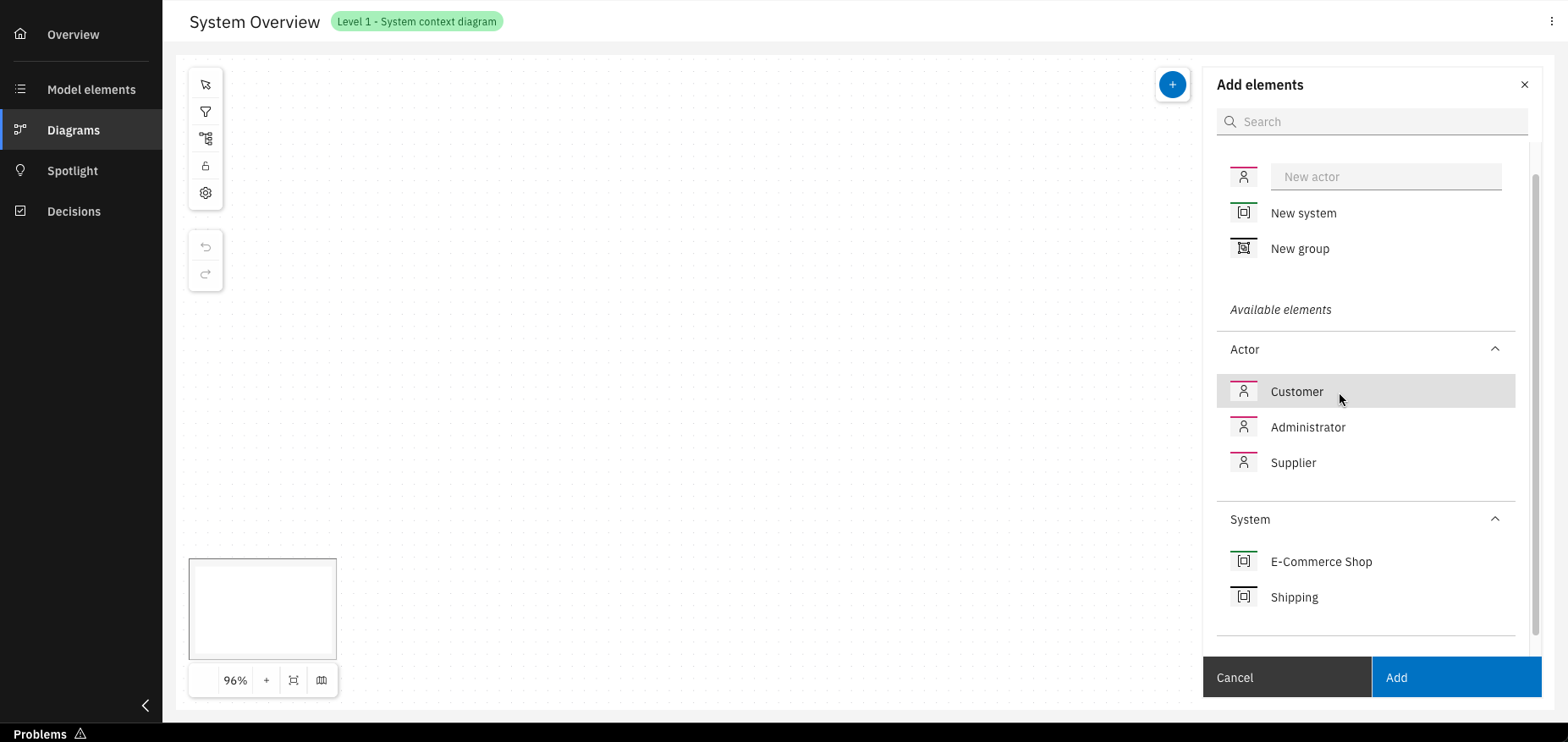
Add existing or new model elements by dragging them in, selecting them and clicking "Add"
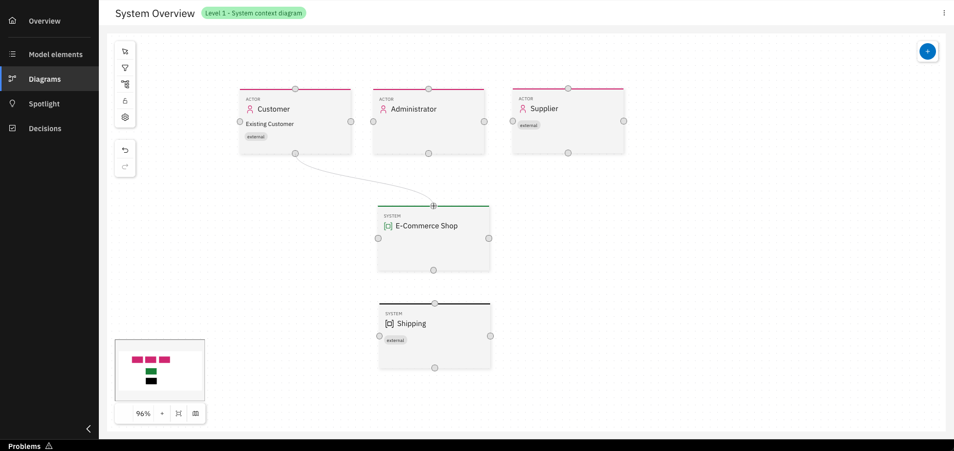
Create relationships between model elements by dragging the relationship arrows
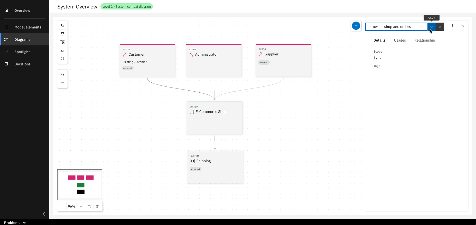
Click on a relationship arrow to open a menu where you can name the relationship
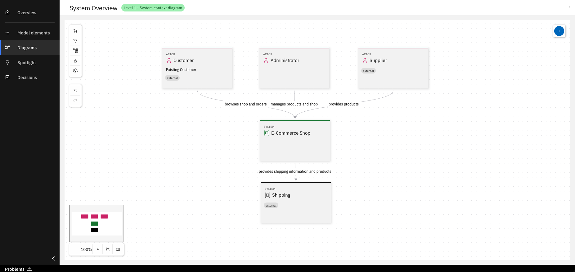
Congratulations! You’ve created your Level 1 diagram
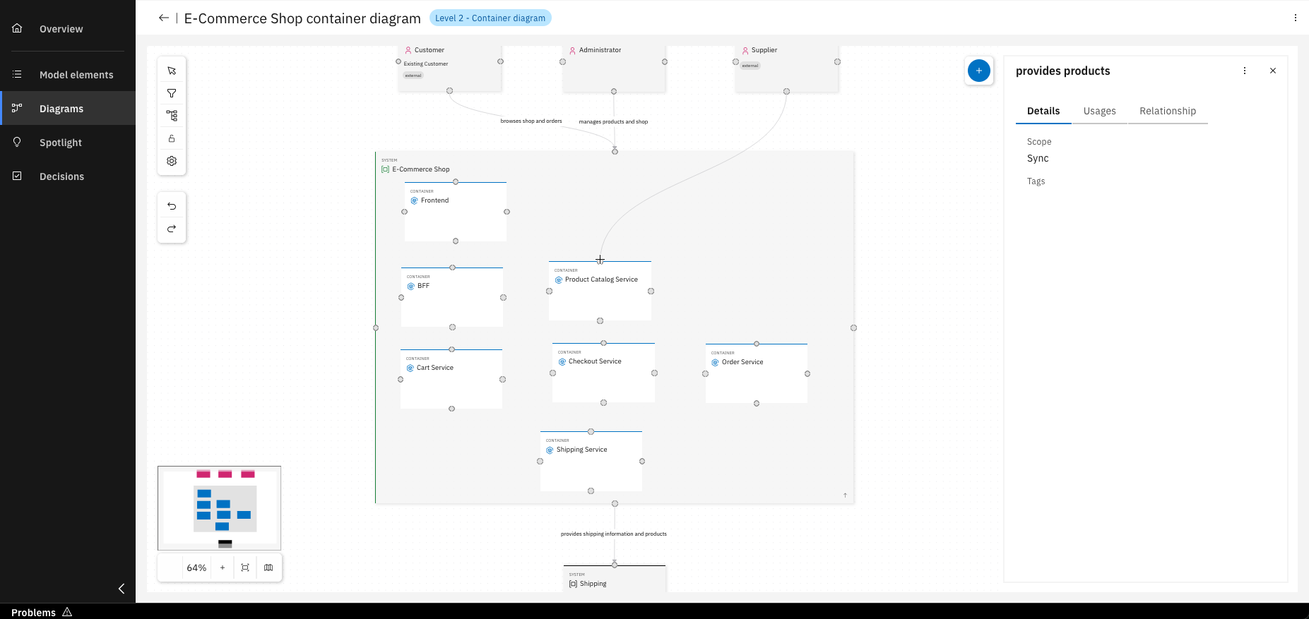
Step 3: Drill down and create a level 2 diagram
Once you understand how your system fits into the overall IT environment, you can focus on the internals of a software system. Therefore, we want to zoom into the system boundary with a Container diagram. This diagram shows the high-level shape of a software architecture and how responsibilities are distributed.
Select a system and click on "Create diagram"
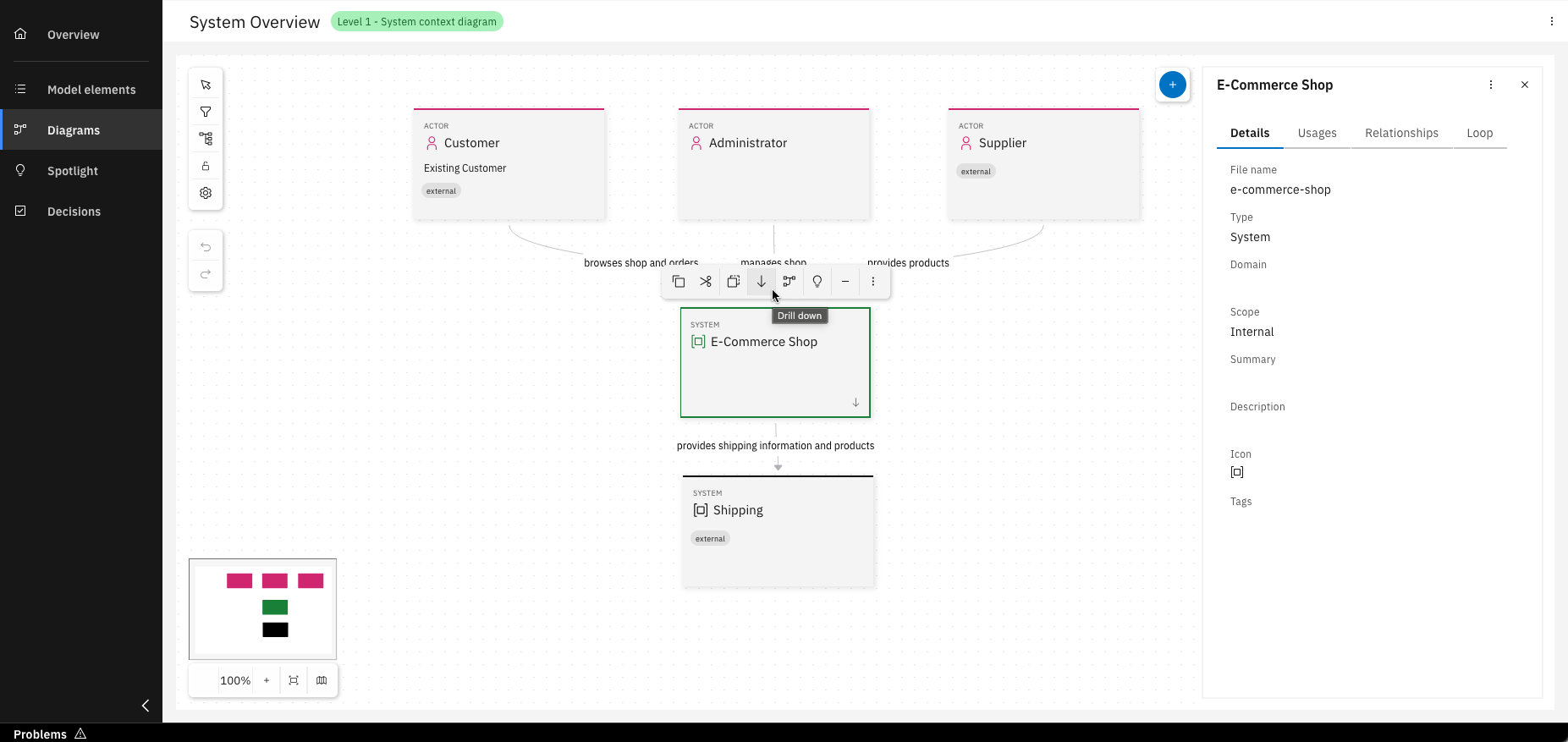
You now have the option to drill down into Level 2
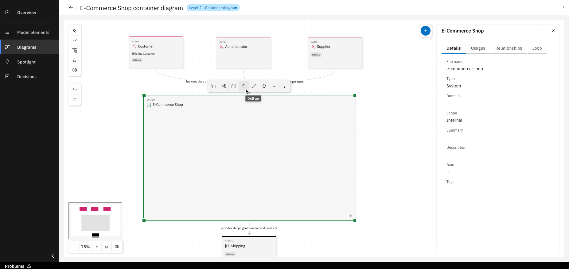
Or drill up from Level 2 back to Level 1
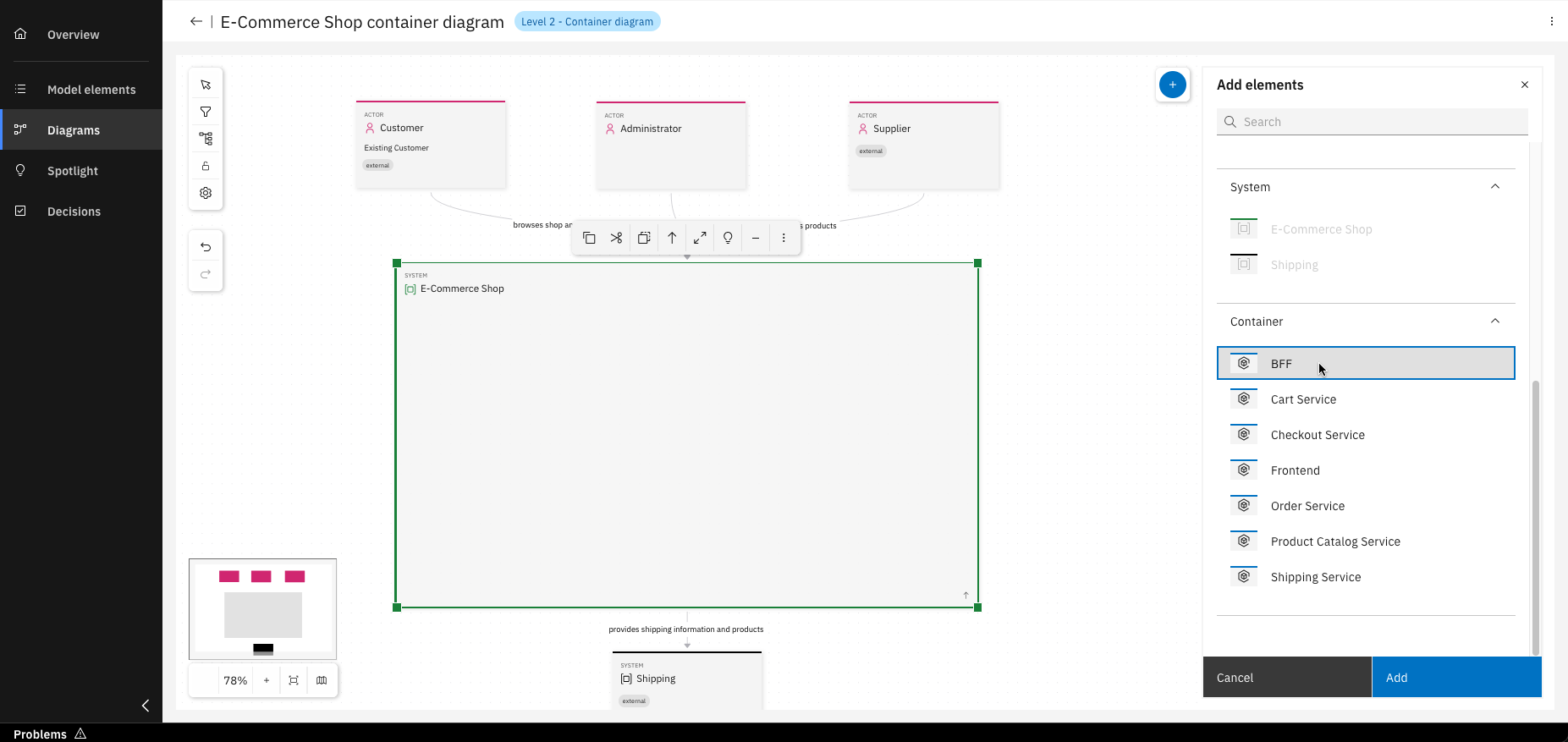
As in Level 1, you can add existing model elements by dragging them in or selecting and clicking "Add"
Relationships from Level 1 are visible here and can be modified, changes will not affect Level 1
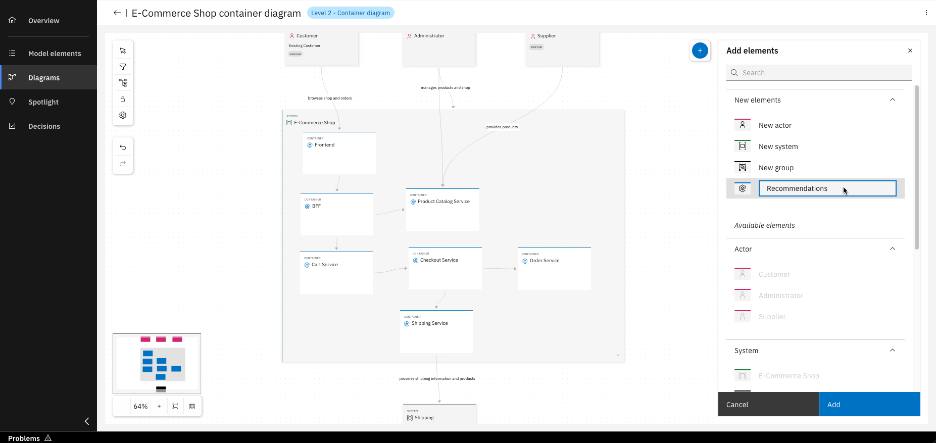
You can also create new model elements directly within the diagram, they’ll appear in "Model elements"
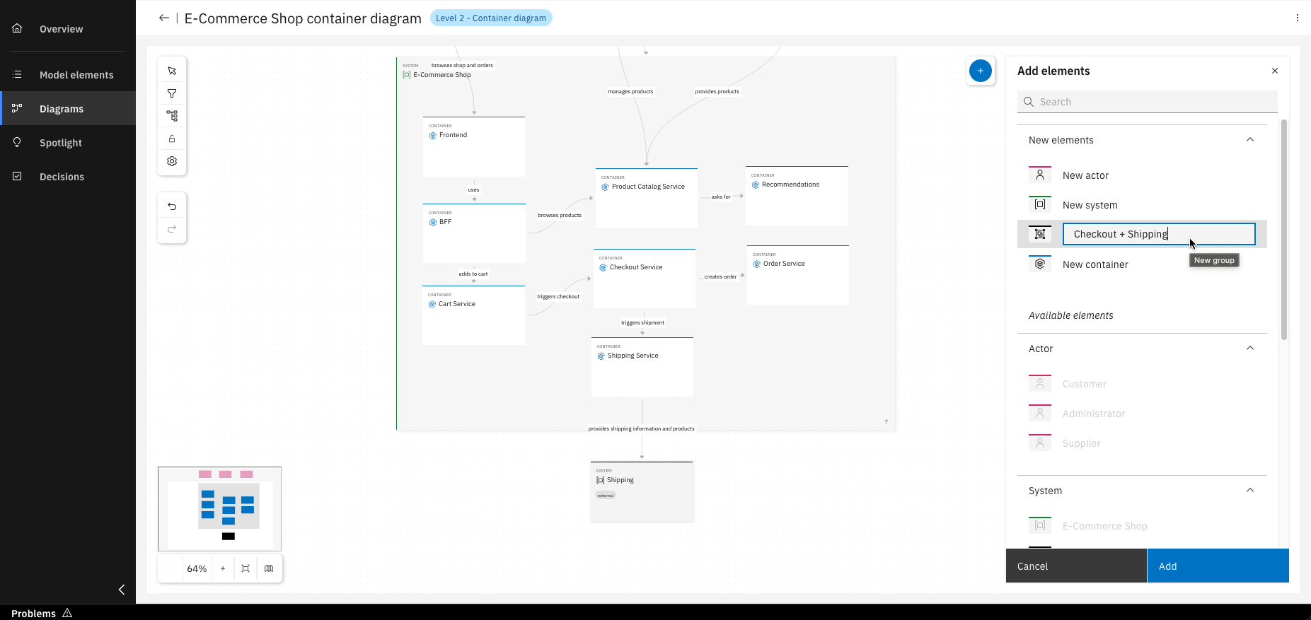
Groups can be created to organize your containers
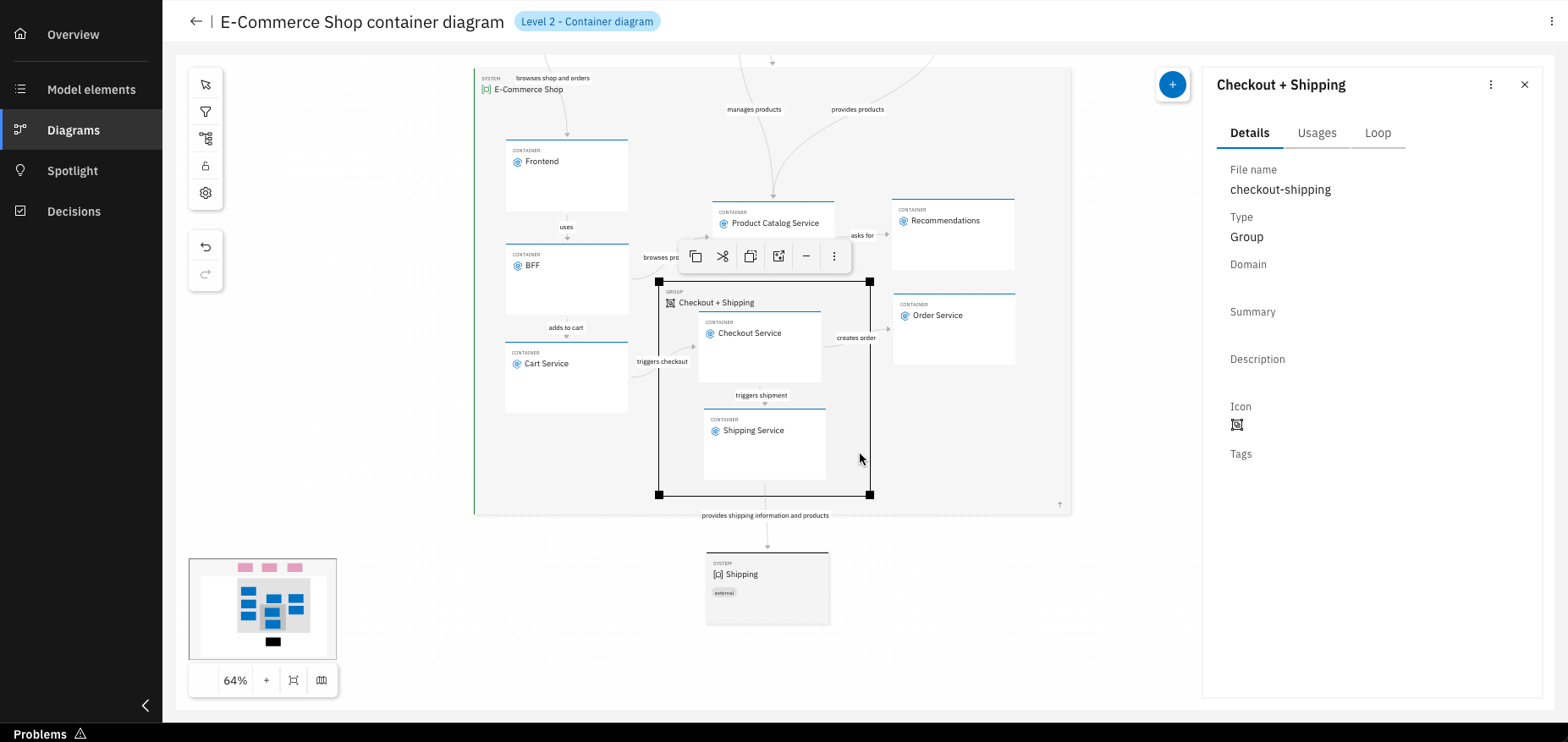
Once created, simply drag and drop containers into the desired group
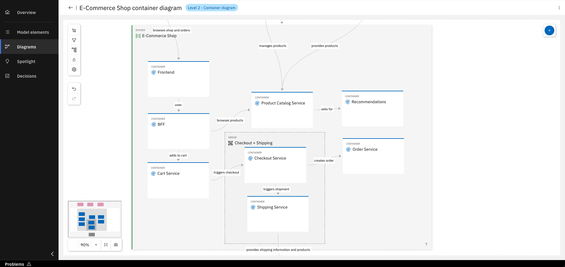
Congratulations! You’ve created your Level 2 diagram
Optional Step: Create a service project out of a component
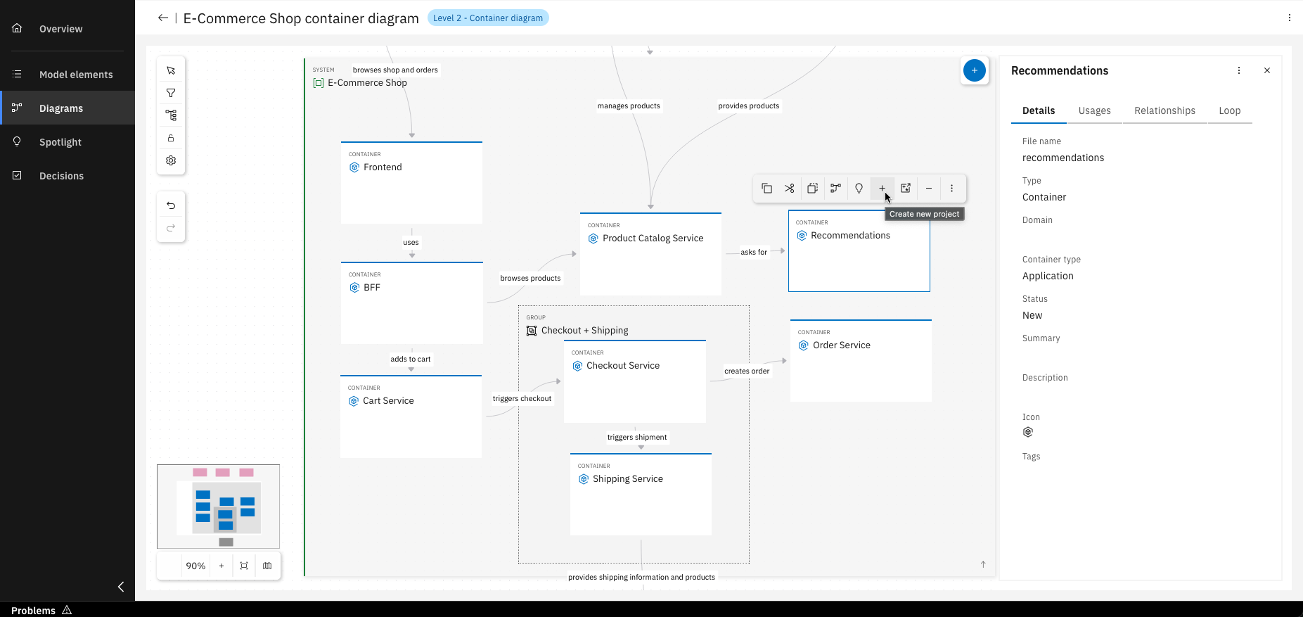
To create a project from a container, click on "Create new project"
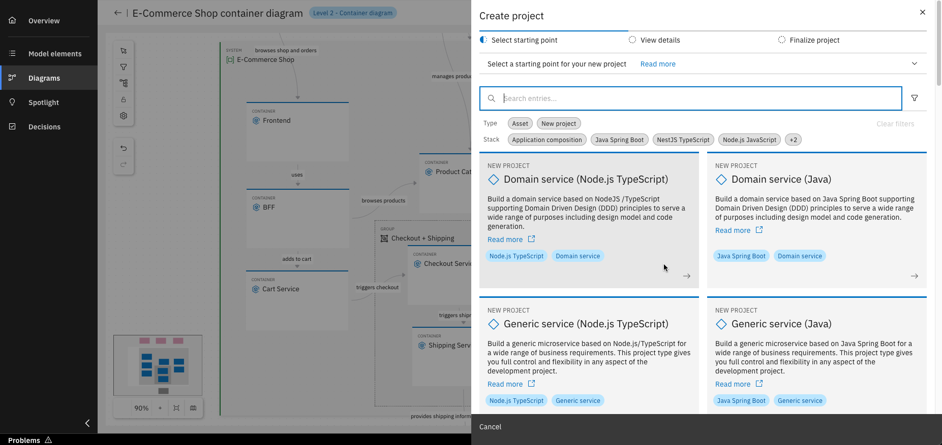
Select the desired service type
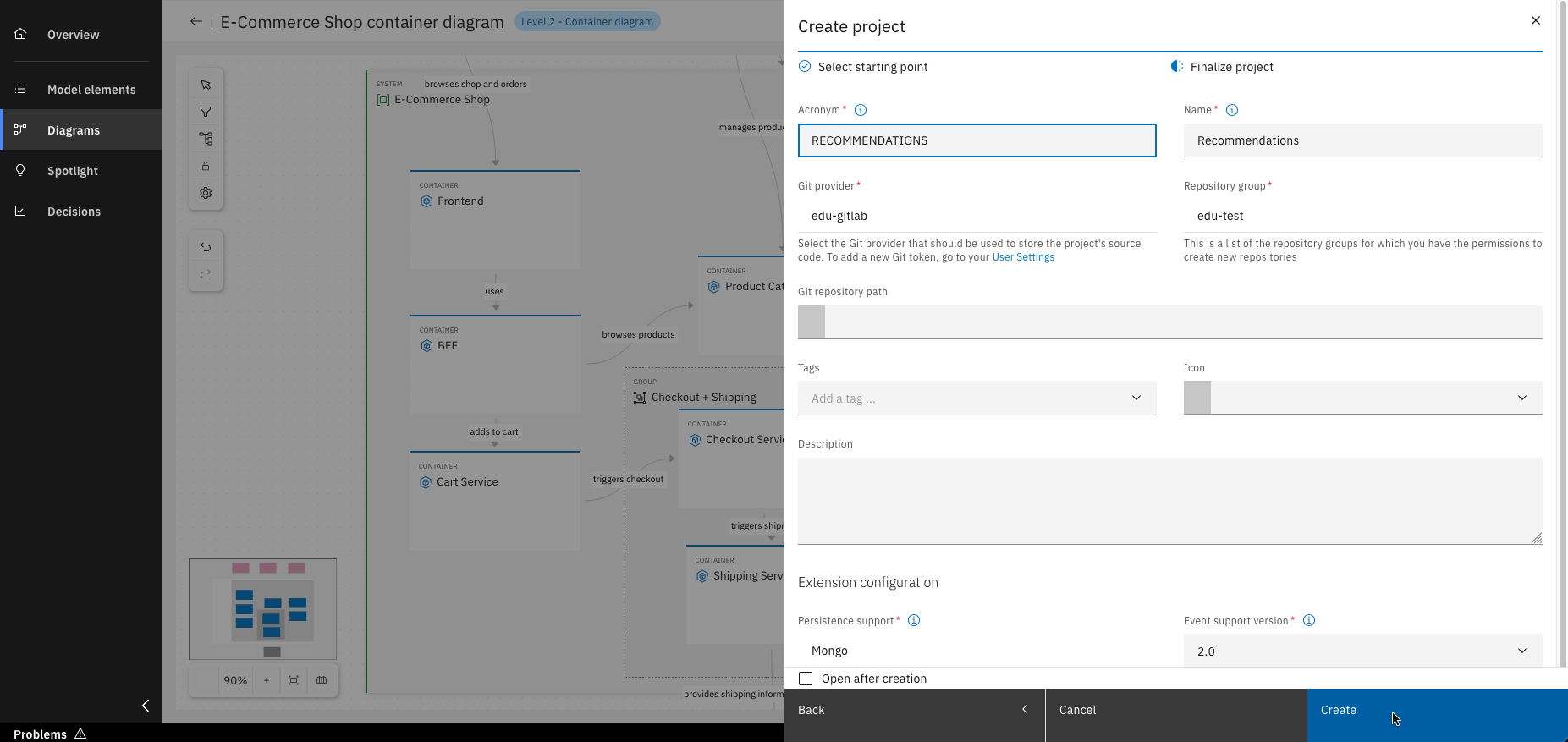
Fill in all required details and click "Create". Just like that, you’ve created a new project based on your model!
For more details on how to create a service follow the Design Journey.
You have successfully created model elements and your first diagrams!
What's next?
In the upcoming units, you will explore each capability of the IBM DevOps Solution Workbench in greater detail. Alternatively, you can start exploring already created applications here.