Use System Architecture Design
You want to design the architecture for your software system using the C4 modeling capabilities of the Workbench.
Overview
In this how-to, you'll learn how to:
- Create a System Architecture Design project
- Model reusable architecture elements
- Create multi-level architecture diagrams
- Use spotlights for understanding system relationships
- Document architectural decisions
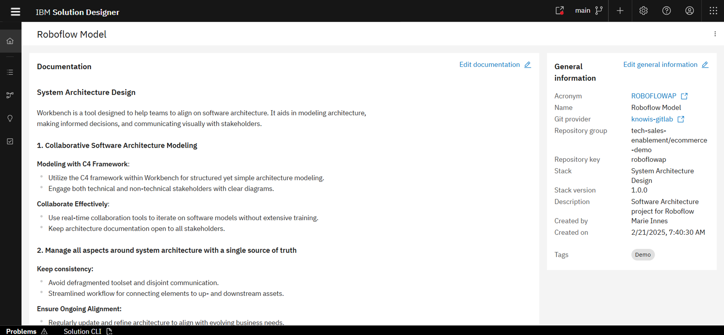
Step 1: Create a System Architecture Project
- Go to the Solution Designer.
- Open your workspace and click Add Project → Create a new project.
- Choose System Architecture Design.
- Fill in the required project metadata:
- Acronym, Name, and Description
- Tags, Icon, and Git Repository Path (auto-generated)
This creates a collaborative space to manage your architectural modeling, documentation, and decision making - all version-controlled and linked to implementation artifacts.
Step 2: Model Your Architecture Elements
Model elements represent core building blocks: Actors, Systems, Containers, and Components.
- Open the Model Elements tab.
- Click Create Model Element.
- Fill out the following:
- Label, File Name
- Type (Actor/System/Container/Component)
- Domain, Scope, Tags, and Descriptions
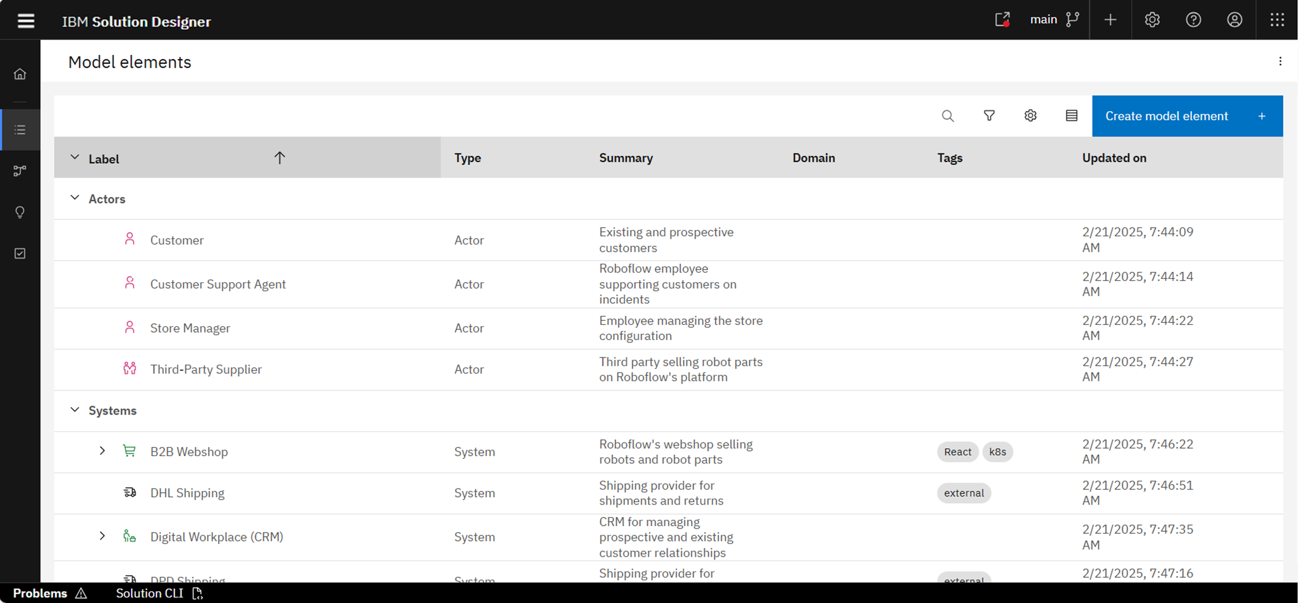
You can define model elements ahead of time or create them directly inside diagrams later. Each element can be reused across diagrams and linked to decisions or services.
After selecting a model element, you can view:
- Details - metadata and domain
- Usages - where this element appears
- Relationships - incoming/outgoing connections
- Loop - linked decisions
For more details, you can check the product documentation: Model Elements
Step 3: Create Multi-Level Diagrams
Diagrams visualize your architecture using the C4 model:
- Go to Diagrams tab → click Create Diagram
- Choose:
- Diagram Type (System Context, Container, etc.)
- Label, File Name, Tags, Domain
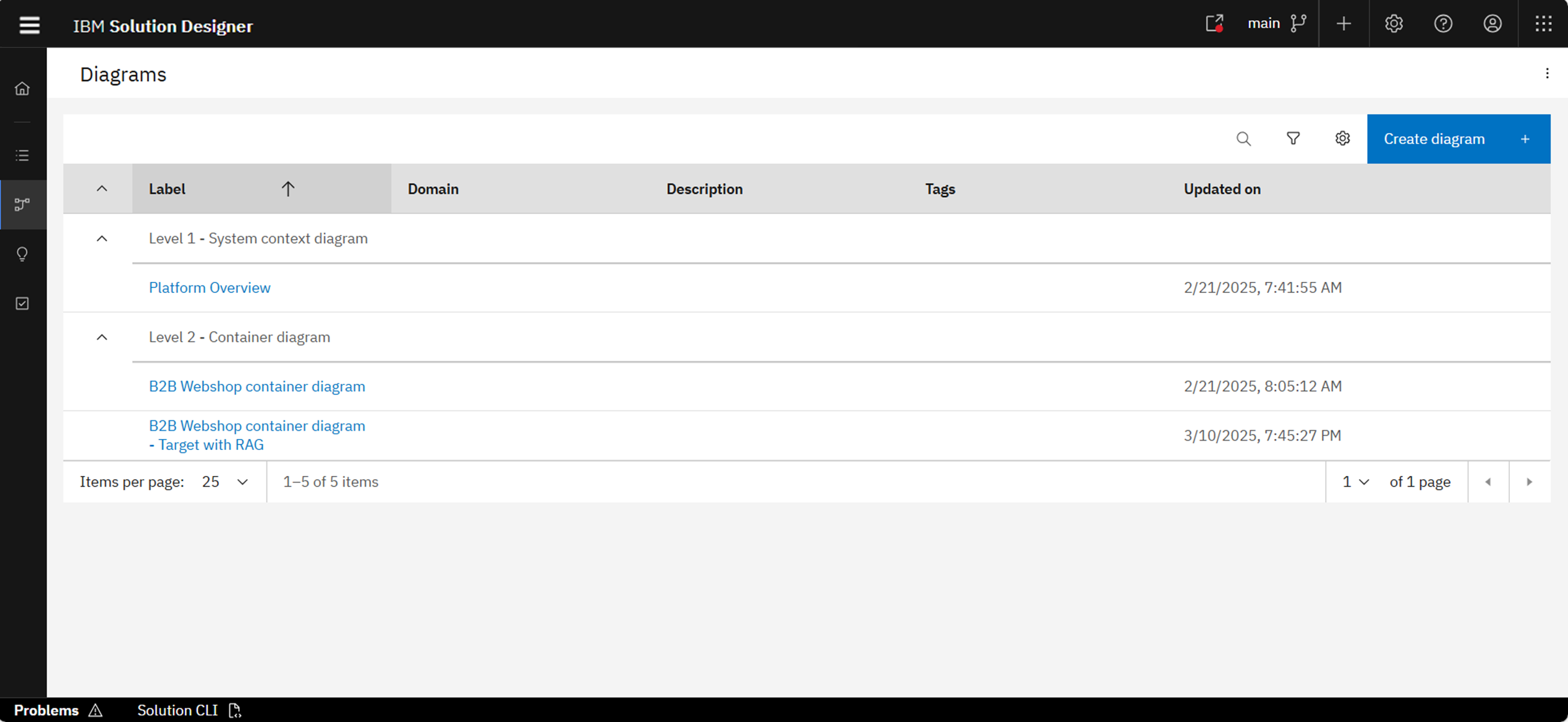
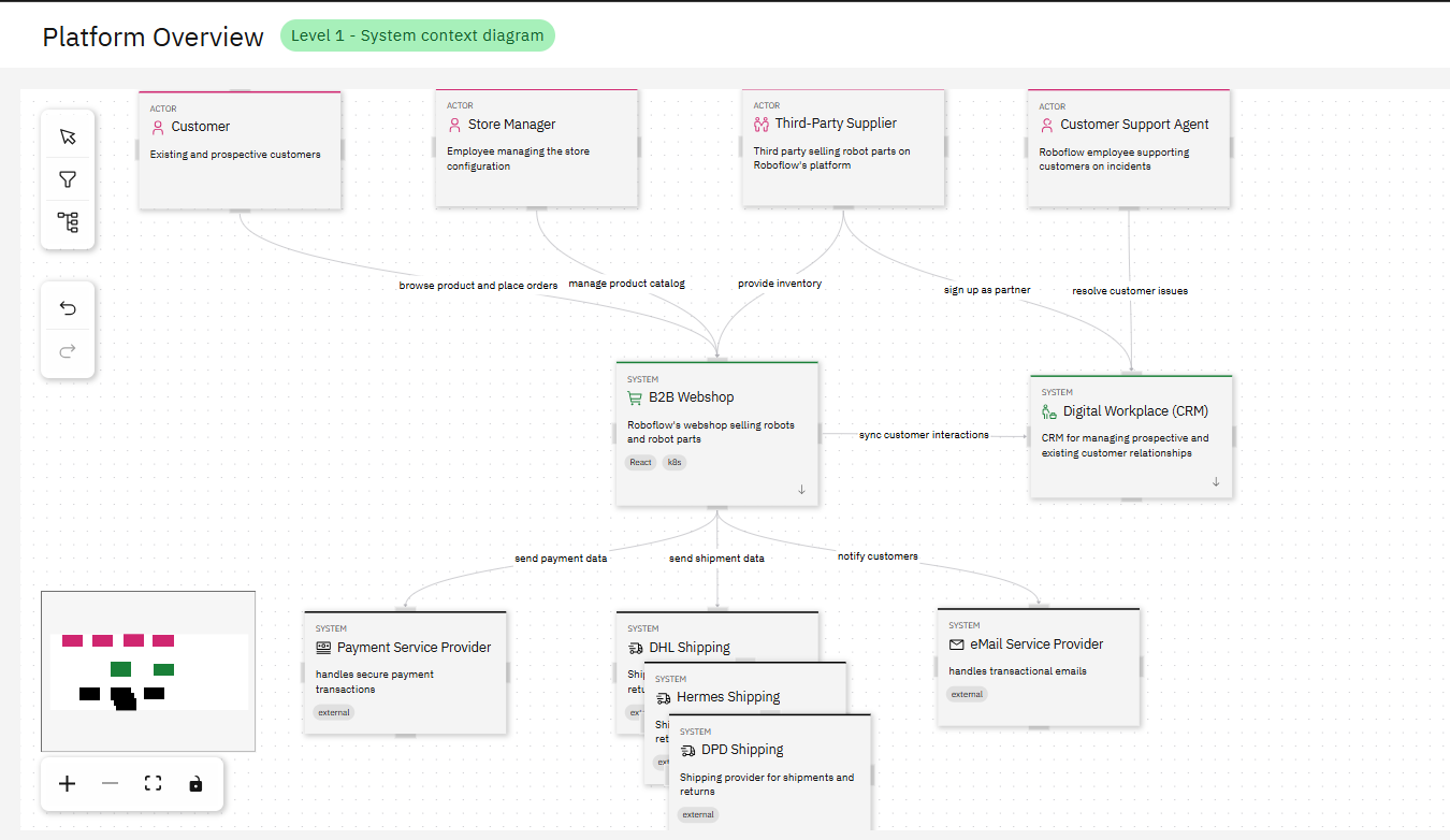
Example: System Context (L1)
Example: Container Diagram (L2)
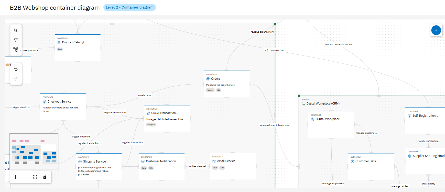
You can zoom, lock, or group elements in diagrams. Elements can be shared, used to generate new projects, or detached. Diagrams evolve with your project.
For more details, you can check the following:
Step 4: Use Spotlight to Explore Relationships
Use the Spotlight tab to inspect any model element and explore all relationships, dependencies, and usages in a visual way.
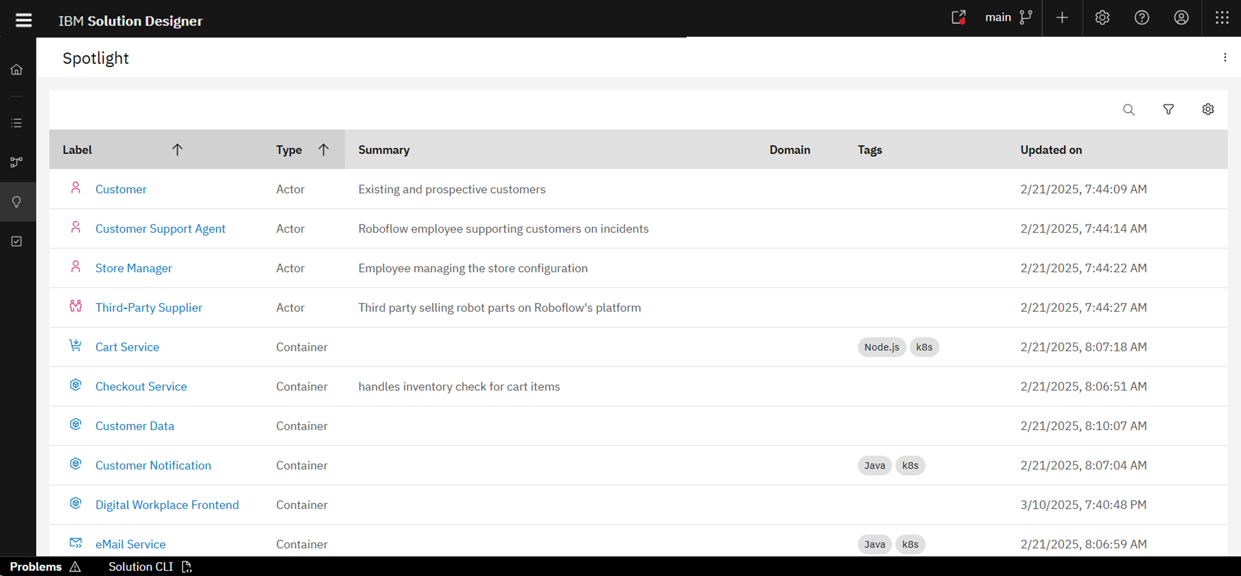
For more details, you can check the product documentation: Spotlights
Step 5: Capture Architectural Decisions
- Navigate to the Decisions tab
- Click Create Decision and fill:
- Title, File Name, Status (Proposed, Accepted…)
- Summary, Tags
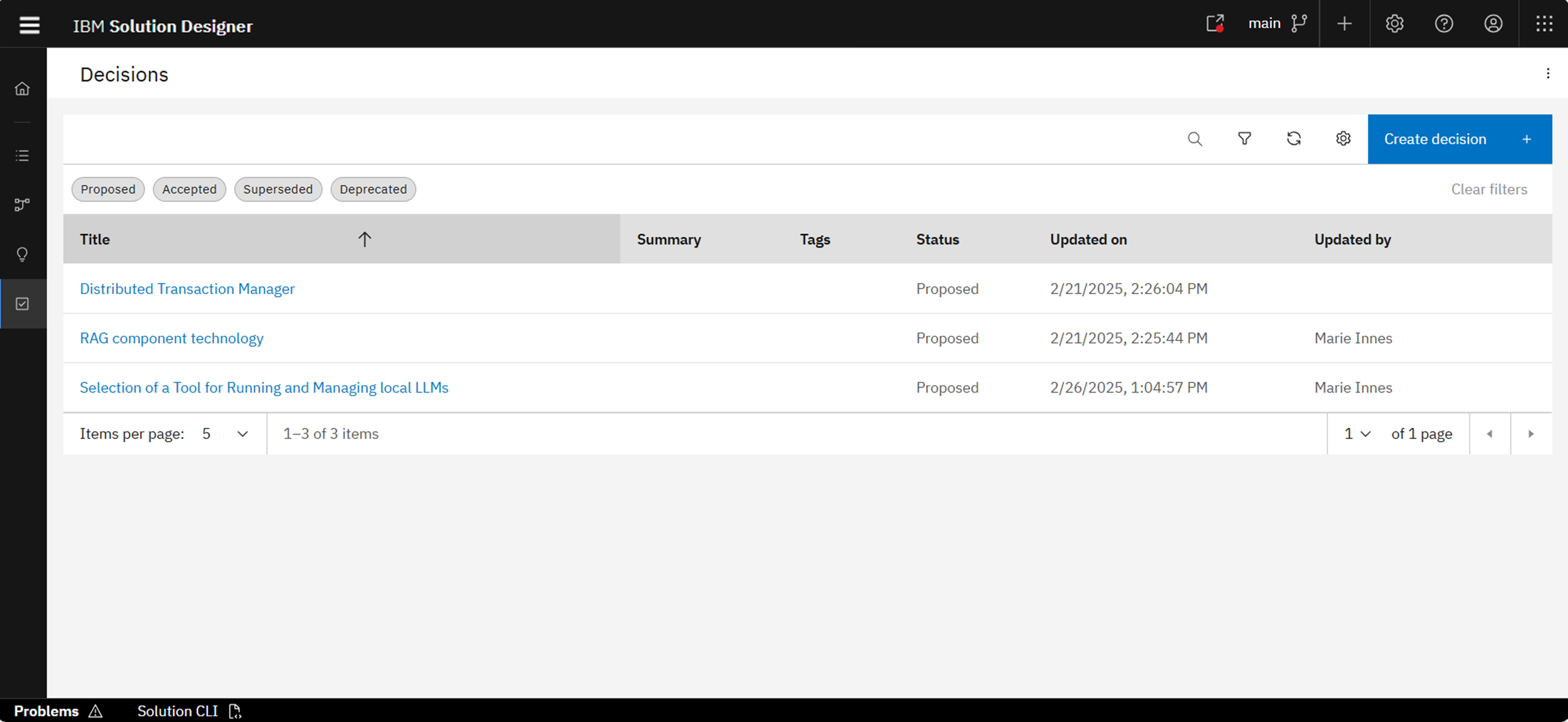
Use the AI-powered ADR Sidekick to auto-suggest decision structure and improve clarity based on templates and your current context.
For more details, you can check the product documentation: Architectural Decisions
You have created a complete architecture modeling project with defined elements, structured diagrams, traceable relationships, and documented decisions.