Architecture
From Vision to Architecture
After identifying the core business goals, modeling the system landscape, and capturing both functional and non-functional requirements, the RoboFlow team moved on to design the target architecture in detail.
Using the Workbench, this step goes beyond static documentation. It's a collaborative modeling process that turns those initial requirements into deployable, production-grade microservices. By following the C4 model, the team incrementally refined their design from a high-level system view (L1) down to containers and components that map directly to running software.
In this section, you'll see how that architecture was brought to life, starting with the project's model overview, then diving into each modeling level — systems, containers, and beyond. Let's begin the journey!
Overview
If you are new to architectural modeling in the Workbench, you can explore more detailed guidance in our Architecture course, but this walkthrough will give you a practical feel for how the tool supports real-world projects.
Let's start with a look at the RoboFlow project's model structure and documentation.
The starting point of the RoboFlow model project is the overview page where you can find two sections: "General information" and "Documentation". "General information" shows you all the basic information of the project like the project acronym, Git Provider, Repository group, the project's description, etc. In the "Documentation" section, you can add all the documentation needed for the project.
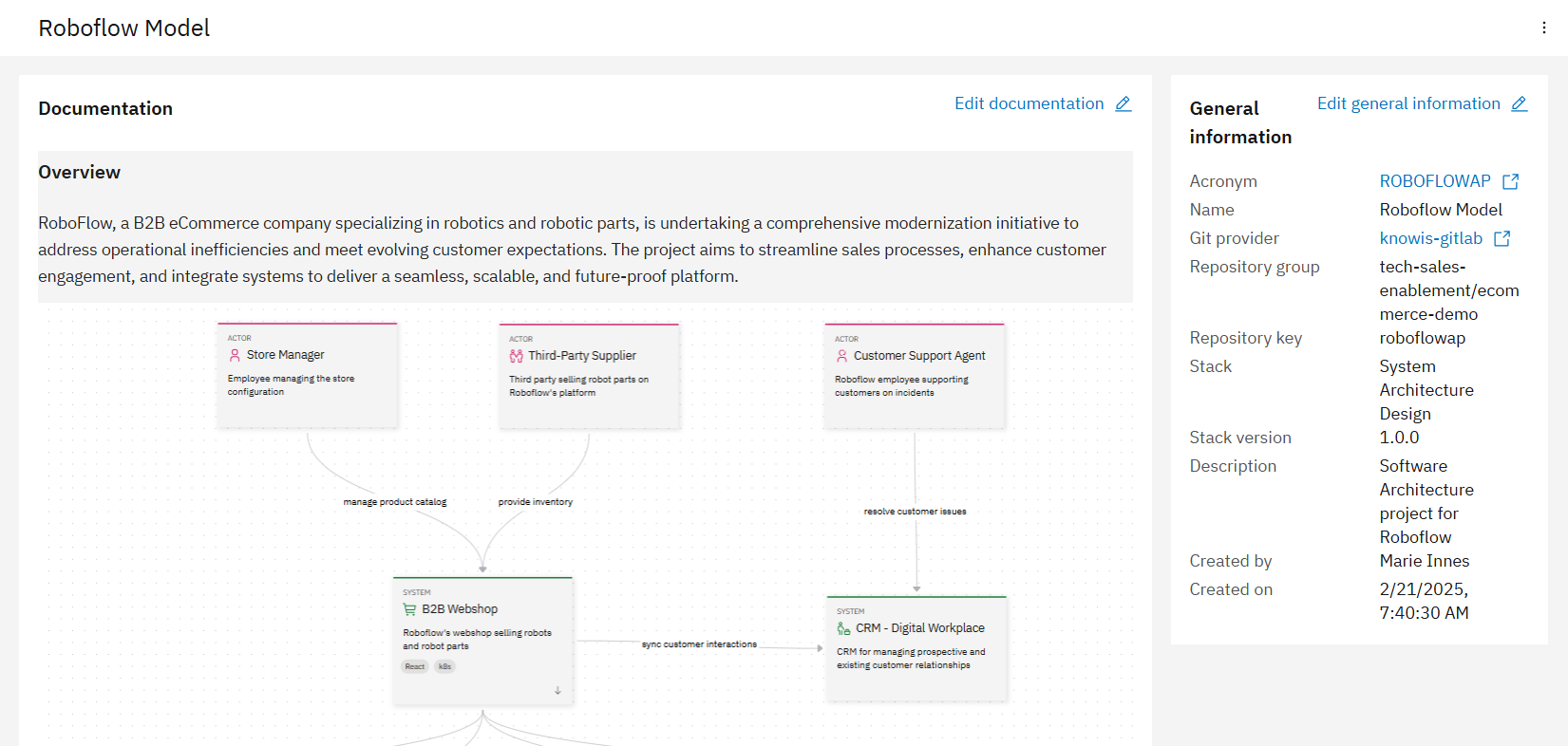
In our project, a software architect has added documentation details in the following structure:
- Project overview with a diagram of how components should be related
- Challenges addressed
- System highlights
- Solution approach
- Development approach
- Current progress
You can view the full documentation here: RoboFlow Architecture Project.
For more information about the overview section, you can visit Product Documentation: Architecture Overview.
Model elements
Next step after documenting the architectural project is to dive in and create all the model elements needed in your project. There are 5 different model element types:
- Actors
- Systems
- Containers
- Components
- Relationships
Actors
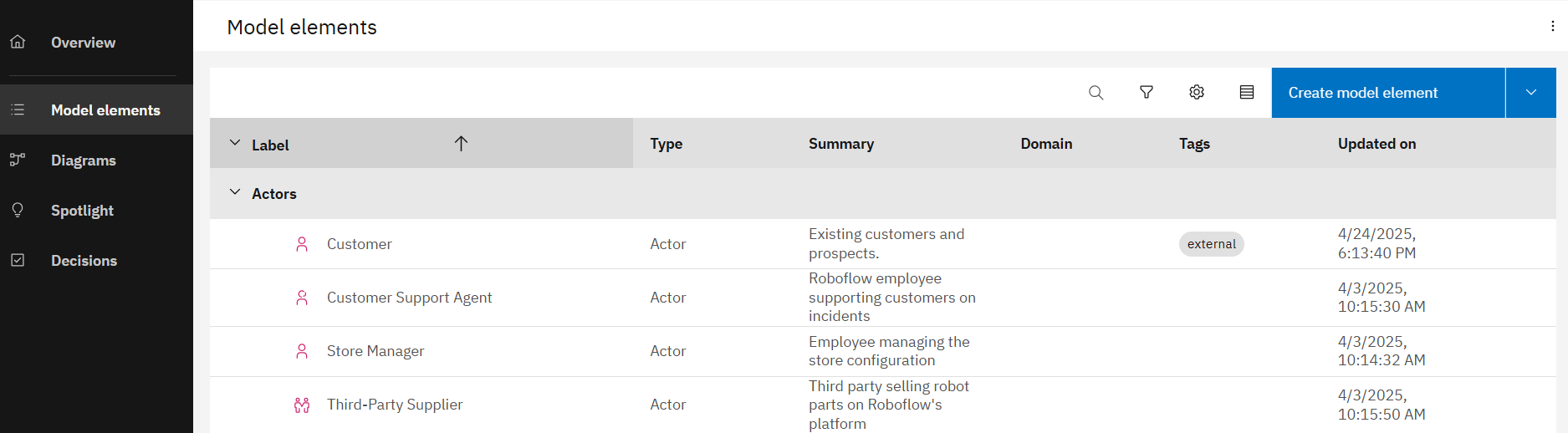
An actor model element refers to people, roles, personas, or named individuals that interact with other components to achieve specific goals. Each actor has a label, file name (a unique identifier for the actor that is used in the repository), domain, scope (either internal or external), summary, description, icon, and tags.
In the case of RoboFlow, the actors reflect the variety of actors identified in the business requirements: from external customers interacting with the webshop, to internal roles like support agents and store managers. These actors help define how the system must behave across different user journeys. In our RoboFlow model, we have therefore created internal and external actors as you can see in the following diagram.
Systems
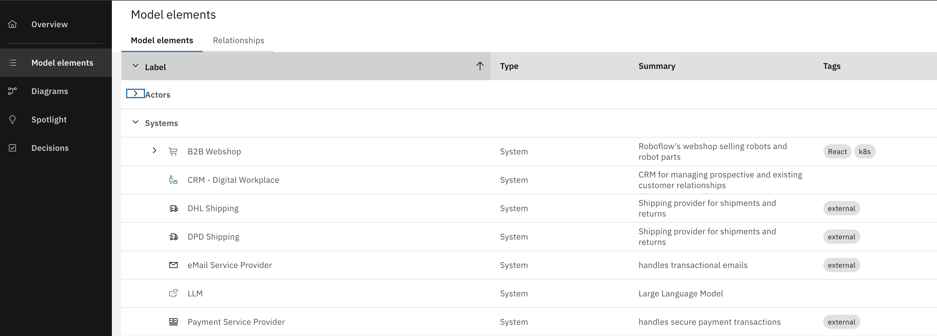
A software system is the highest level of abstraction and representing a solution that provides value to its users, whether they are human or not. This includes the software system being designed as well as the interconnected software systems it relies on or supports. Each system has a label, file name (a unique identifier for the system that is used in the repository), domain, scope (either internal or external), summary, description, icon, and tags.
For RoboFlow, the modeled systems reflect the platform ambitions described earlier, namely, building a modern eCommerce platform alongside an integrated CRM solution. For their customer-facing and internal use cases, they rely on each other as well as external systems, as shown in the following table.
Containers
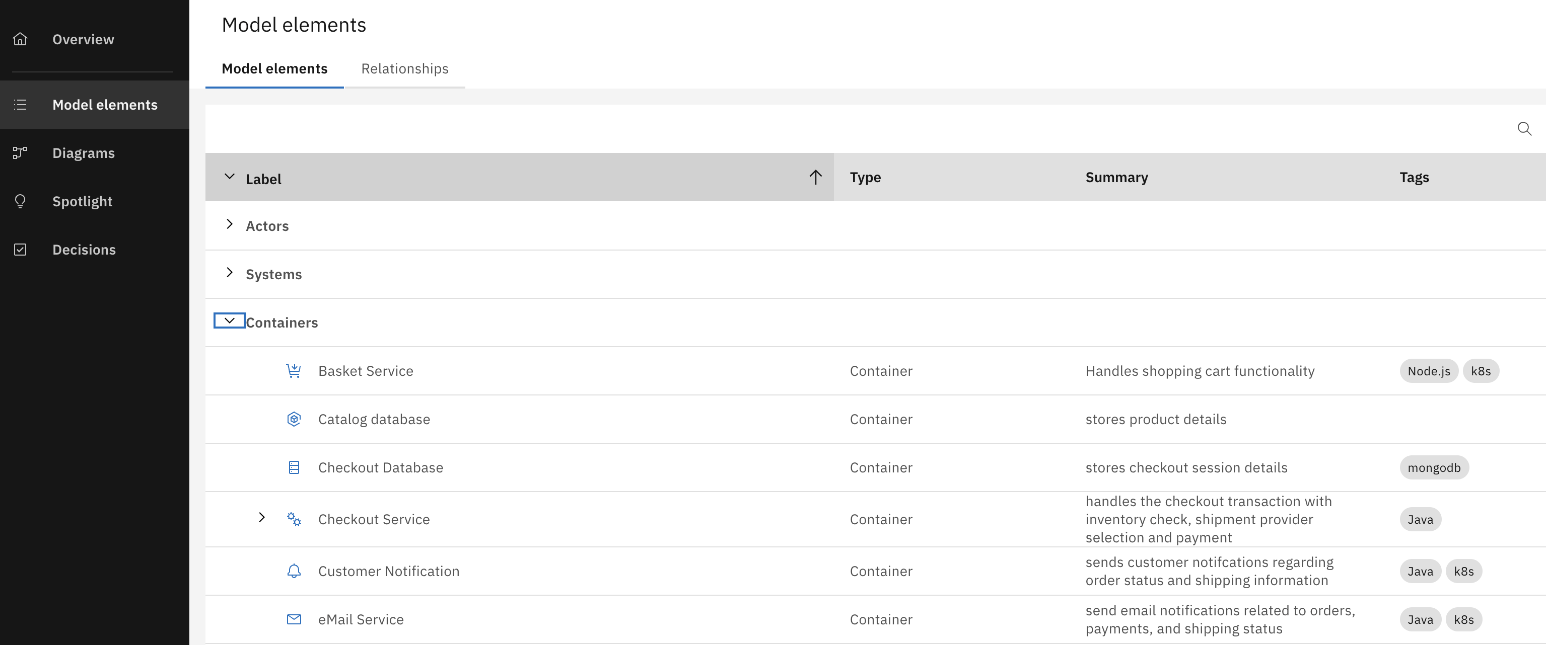
A container model element refers to a runtime component or deployment unit that encapsulates a portion of the system's functionality. Containers are intermediate-level components that sit between the high-level system and low-level code or modules. They represent the physical or logical boundaries where code is executed and data is stored, providing a clear structure for understanding how different parts of the system are deployed and interact at runtime. Each container has a label, file name (a unique identifier for the container that is used in the repository), domain, container type (application or datastore), status, summary, description, icon and tags.
In the RoboFlow model, containers reflect how key business capabilities, such as product browsing, checkout, order processing, or CRM case management, are separated into deployable services. As RoboFlow's requirements evolved to serve both customer-facing and internal workflows, container boundaries became essential in isolating responsibilities and enabling independent development and scaling. Several containers have been created as shown in the following table.
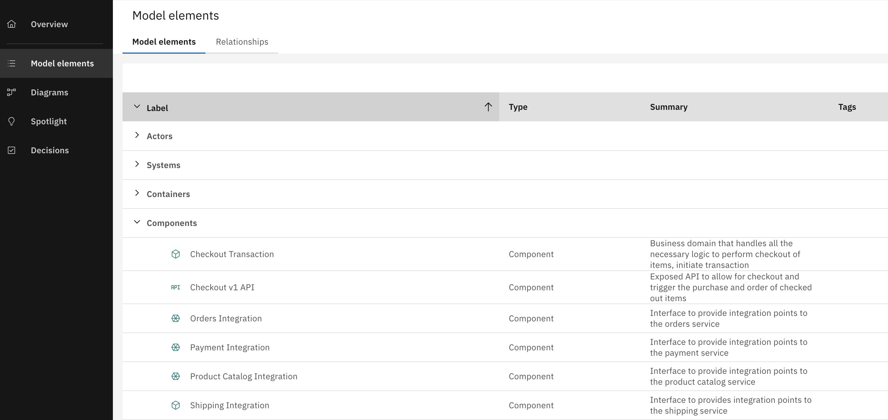
Components
A component is a group of related functionality encapsulated behind a well-defined interface. Components themselves are not independently deployable. Rather, the container serves as the deployment unit, meaning all components within it run together within the same process space. Each component has a label, file name (a unique identifier for the component that is used in the repository), domain, summary, description, icon and tags.
In the RoboFlow model, components reflect how specific features and responsibilities are structured within a service. For example, handling order submission, payment processing, or browsing products. As the platform grew, some components had to expose separate interfaces to support different user roles and workflows. In the case of order management, this led to a clearer separation between customer-facing and internal order interactions. A shift that will later be reflected in dedicated API paths. Several components have been created as shown in the following table.
Relationships
There are several relationships between the different containers. The following are all the relations between the containers that you can also see later in the L2 diagram:
- The customer is the external actor that browses products and place orders from the B2B webshop system; specifically the Webshop Fronend.
- The webshop frontend container uses the Webshop Backend-for-Frontend container as an intermidiary to access other services like the basked service and the product catalog.
- The Webshop BFF
- Browse products from the Product catalog service.
- Adds to cart from the Basket service.
- Besides the product catalog relation with the Webshop BFF, it also has other relations to other services:
- The store manager manages the product catalog from the service.
- Third party suppliers provide inventory into the product catalog service.
- The checkout service checks the inventory using the product catalog service
- The basket service triggers checkout using the checkout service.
- Besides the relation between the checkout service and the basket service, it also has other relations to other services. The checkout service:
- Creates an order into the orders service.
- Stores data into the checkout database.
- Triggers shipment into the shipping service.
- Registers the transaction into the SAGA transaction manager service.
- The orders service then syncs the customer interactions with the CRM - Digital workplace system.
- The shipping service sends the shipment data to DHL shipping and DPD shipping systems. It also triggers a notification in the Customer Notification service.
- The customer notification service then triggers an email notification in the eMail Service.
- Finally the eMail Service then notifies the customer via the eMail service provider service.
For more details on model elements, you can check the product documentation: Product Documentation - Model Elements.
Diagrams
In the architecural diagrams section, an architect is able to create diagrams at different levels following the C4 notation, explaining relations betwen elements in different level of detail. In RoboFlow, we have created several diagrams, in this article we will focus on two diagrams:
L1 - Solution Overview
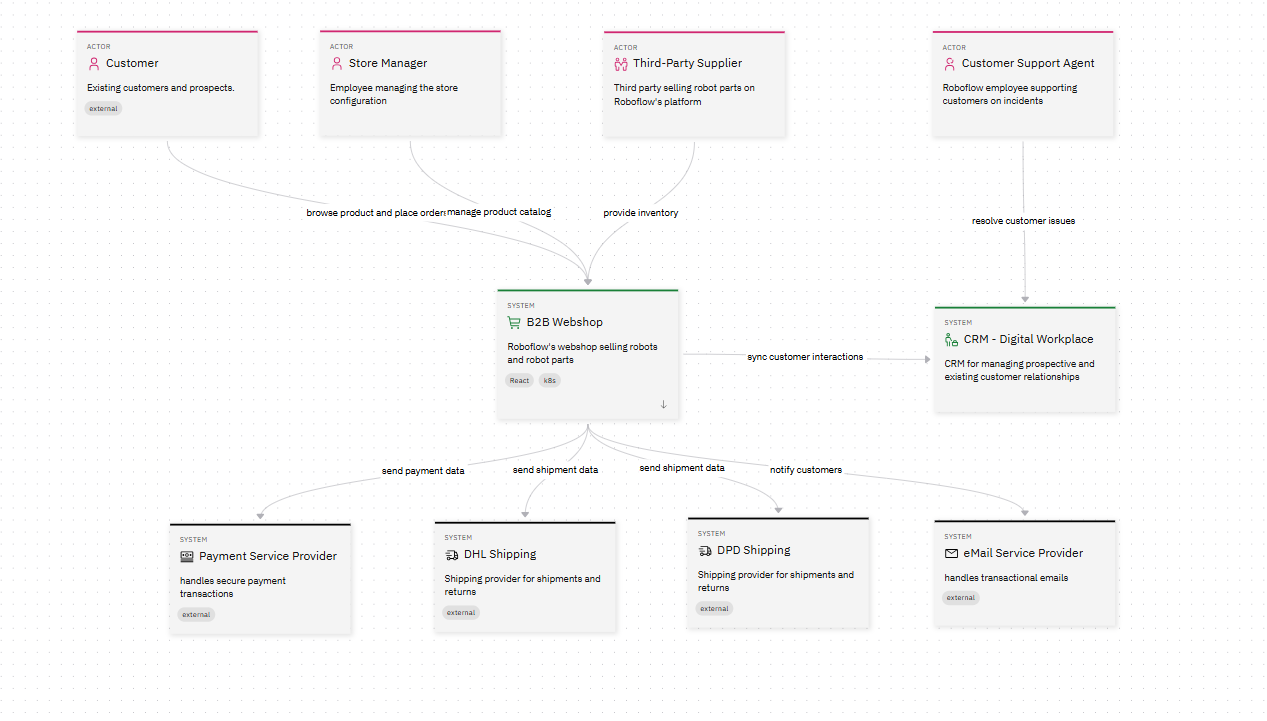
As you can see in the diagram above, it is divided into two main systems, eCommerce platform and CRM system. The diagram also illustrates the bidirectional data sync which ensures consistency between both systems, enabling features like dynamic pricing adjustments and predictive reordering. Moreover, the diagram shows different third-party integrations where it connects to external systems such as payment gateways, shipping providers, and product catalogs to extend functionality.
For an interactive version of the diagram, visit RoboFlow Solution Overview Diagram
L2 - B2B Webshop container diagram
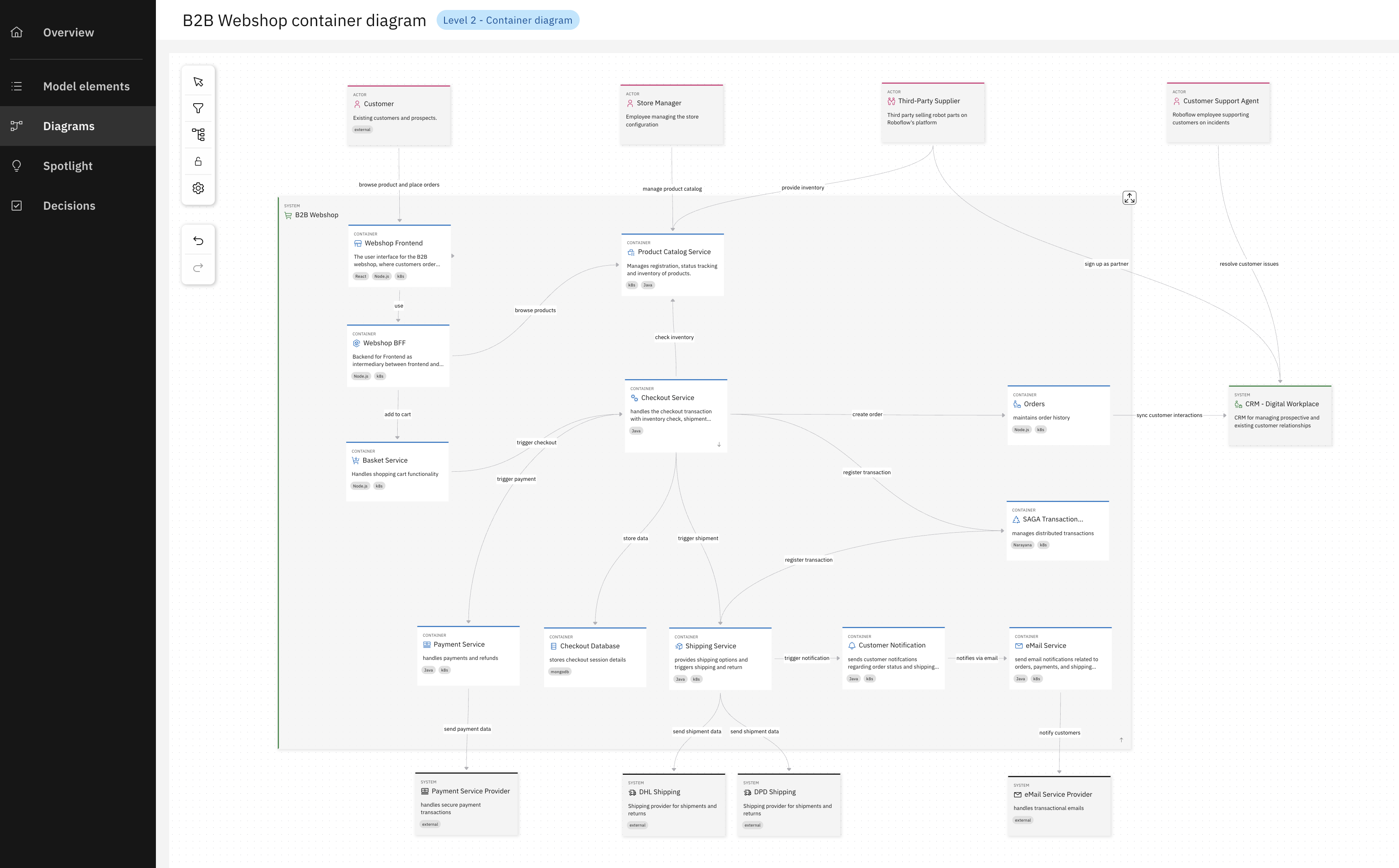
The second diagram provides a detailed yet high-level visualization of the runtime architecture for the B2B Webshop, a critical component of the RoboFlow platform. The diagram above highlights the runtime components (containers) of the B2B Webshop, emphasizing their roles, responsibilities, and communication patterns. It serves as a reference for understanding how the webshop operates at runtime, ensuring scalability, resilience, and seamless integration with other parts of the RoboFlow platform.
For an interactive version of the diagram, visit RoboFlow B2B Webshop Container Diagram RoboFlow B2B Webshop container diagram.
For more details on architectural diagrams, you can check the product documentation: Product Documentation: Architecture Diagrams.
Decisions
The Architecture Decisions page serves as a reference for stakeholders, architects, and developers to understand the strategic choices made during the development of the RoboFlow platform. Each decision is documented to ensure transparency, alignment with business goals, and consistency across the system. This documentation also helps onboard new team members and provides a historical record of why certain approaches were chosen over others. In the architecural decisions section, an architect is able to document and process decisions related to the architectural project, exploring solution options, explaining their rationale and documenting the chosen approach. In RoboFlow model, we have created and documented several decisions throughout the architectural design and implementation as you can see in the following table.
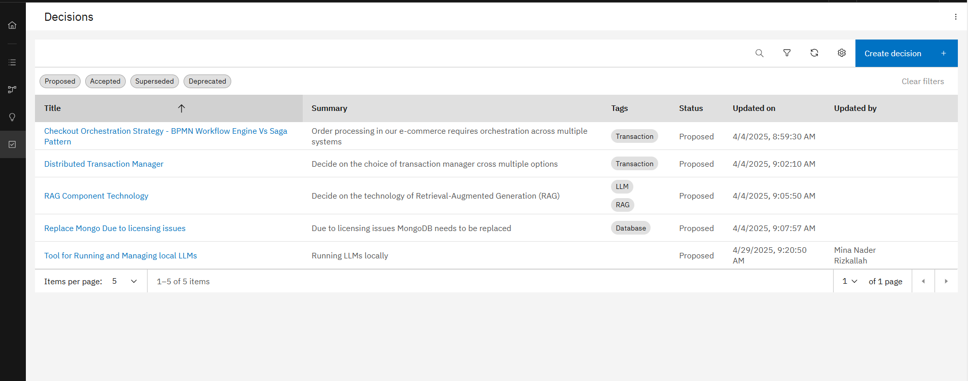
Creating decisions is fast and effortless thanks to the ADR Sidekick — our context-aware Gen-AI assistant. What makes it powerful is that it understands the context of this specific project, including all the related components, documentation, and predefined templates. It also takes into account your enterprise's architectural rules and constraints, so the generated content is not only relevant — it's aligned with your standards and ready for approval.
For an interactive view of the architecture decisions, visit RoboFlow Architecture Decisions.
For more details on architectural decisions, you can check the product documentation: Product Documentation: Architecture Decisions.